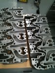
Porting to reach high rpm breathing

Fahlin Racing

New member
Aug 22, 2012
330
0
0
NE Ohio
Thank you Ben, now I know how much area I have to play with. Thanks for the link Blk Smoke, that is one pretty kool looking manifold. I think I will skim through that thread too.
 

Fahlin Racing

New member
Aug 22, 2012
330
0
0
NE Ohio
The route of the LMM intake routes. Guy told me the only difference is the way the injector pocket is machined compared to the LML.
Dmaxlmm4route_zpscfbff7eb.jpg


As you can see, as you move to the left on the heads viewing from the intake side you have 2 cylinder's intake ports next to each other which will give you different wave tuning as the valve train does its job.
 

Fahlin Racing

New member
Aug 22, 2012
330
0
0
NE Ohio
Getting closer, I have been looking at more porting tips for the grinder here and getting other things tied up and finished. My idea of combining the runners for breathing is simply that, not to just have a plenum store our main bulk density but have some down closer to the valve. Now I must start thinking about each cylinder in relation to each other to see when each will be allowing our charge in. That portion will take a little bit but that will be on the back burner. For now I am just going to grind and shape here coming up soon. Still have the PS project on hold while I do some so that is why I am at a pause for now.

Anyone care to voice what they think may happen in this project, I am thinking I may have to have the port mapped before I grind. Air doesn't like sudden changes in CSA so I will just ponder for a little bit on how I may go about this.
 

Fahlin Racing

New member
Aug 22, 2012
330
0
0
NE Ohio
I should point out, the two ports next to each other are different cylinders, I know thats obvious but I wan to clarify that anyone questioning knows. This is the reason why I mention that I need to look at each cylinder's opening point and look to when the two flow paths will react with each other.
 

Fahlin Racing

New member
Aug 22, 2012
330
0
0
NE Ohio
Mark, great addition to the thread. Ben, thats in the general idea of what I have planned. Joining them until they must split.

From the picture it looks like they removed a couple inches into the head. The radius itself shows me they are still using a plenum type of intake like the factory one, I could be wrong with my assumption though on what manifold is ran on these heads. What I want to determine is where the main flow path is and go at it in that respect. I will not actually be employing a radii around the runner entry.

Brings up some interesting thoughts.
 

Fahlin Racing

New member
Aug 22, 2012
330
0
0
NE Ohio
Have a small question here, I found a firing order for these mills. Just want to verify this is the correct firing order for a Duramax, 1-2-7-8-4-5-6-3. With the passenger side as the leading bank.
 

3500gmc

Still plays with trucks
Mar 15, 2013
14
0
0
East Central Ohio
They make a rubber material that's in a can. The old timer head porters use it. You brush it in the port, it cures and you pull it out. It springs back into shape creating a model of the inside of your port. It could shed some light on where the port needs help.

Bigger ports usually means you need bigger valves also.. Not always, but usually.

It's widely known that 'blending the bowls', unshrouding the valves, cleaning up the short side radius will wake any cyl head up.
 
Last edited:

MadMaxx61

Devilmaxx
Oct 13, 2008
5,458
1
36
39
Windsor, Ont, Canada
They make a rubber material that's in a can. The old timer head porters use it. You brush it in the port, it cures and you pull it out. It springs back into shape creating a model of the inside of your port. It could shed some light on where the port needs help.

Bigger ports usually means you need bigger valves also.. Not always, but usually.

It's widely known that 'blending the bowls', unshrouding the valves, cleaning up the short side radius will wake any cyl head up.

plasti dip not the spray can stuff be the stuff to make handles on tools works well for this.
 

Fahlin Racing

New member
Aug 22, 2012
330
0
0
NE Ohio
Yeah, I will grab some silicone from somewhere. I recently bought up some epoxy from Reher-Morrison for my PS head work since I dont have a welder to fill.

Mark's photo, I appreciate being to use you photo Mark, thank you. here I have pointed out a hole. What is this hole meant for?
Dmaxcuthorizontal00_zpsaa31657d.jpg
 

JoshH

Daggum farm truck
Staff member
Vendor/Sponsor
Feb 14, 2007
13,606
641
113
Texas!!!
I believe that is the hole that feeds oil to the rocker shaft.
 

Fahlin Racing

New member
Aug 22, 2012
330
0
0
NE Ohio
Alright, thank you for the information. The walls in these heads seem to be borderline as far as wall thickness. The runners that turn at a what 75 degree turn are the most symmetrical throughout and the straight-to-the-valve runners seem to bottle neck, I haven't gotten my heads apart yet but from the picture the most meat seems to be in the bowl's area. The runners hugging the oil pressure feed hole would have the longer set before the partition is removed but going over the firing order the cylinders that share runners where the divider is going to be removed shouldn't cause any flow interference, at least in my premiss here, the only thing that will effect cylinder fill is the CSA change from larger joined portion of the port to the smaller runner, air doesn't necessarily like doing it but from what I have read its not as bad as air going into a larger area abruptly.