How To: LMM OS - MAP Scaling

kidturbo

Piston Tester
Jul 21, 2010
2,319
1,081
113
Somewhere On The Ohio
www.marinemods.us
For anyone looking to improve resolution in MAP related tables, or increase the output range of boost reading on displays.

The long version of this discussion: http://www.duramaxdiesels.com/forum/showthread.php?t=70615

Default LMM OS MAP sensor scale reads 0-366 kPa or 0-53.1psi sensor input range. This is a hard set value, with no adjustment options in EFIlive.

Should also be noted this is uncorrected boost reading from PID's GM.BOOST2_DMA or MAP2 and does NOT match up with OBDII PID SAE.MAP [which is useless in my findings]. To see calculated or corrected boost values, we use (MAP2-BARO) gives you same digital reading as a mechanical boost gauge.

To work with higher pressure values than the stock 3.5 bar GM sensor you need to change the MAP sensor and rescale the values using EFIlive.

--

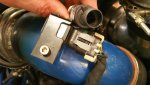
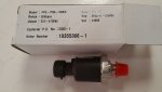
(1) Purchase a 5 or 10 bar 0-5V pressure transducer to fit your build. Fleece keeps these in stock. An older topic here on the LB7/LLY 10-bar mod used a Honeywell sensor I believe. These require a spare 1/8npt port, and changing the factory harness Metripack connector to match. We scavenged one from a spare harness.


attachment.php


attachment.php


attachment.php


--

(2) Once you have the hardware, need to add some cax files to EFIlive directory:
C:\Program Files (x86)\EFILive\V7.5\Calibrations\

** I have attached these 3 cax files here in "lmm-map.zip" below. They will cover standard and DSP OS 12628594 versions.

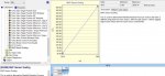
(3) Open your LMM tune in EFIlive and go to Table "B3499" or look under Boost Control for a new table called "Map Sensor Scaling"


attachment.php


--

Depending on your default unit settings Imperial or Metric, this scale will be PSI or KPA. Suggest using metric to keep it simple.

The lower value shouldn't change, while the upper limit should be set to match your new sensor.

IE: 5BAR is 500.0kpa or 72.518869 PSI absolute


attachment.php


--
(4) Save your new tune file and test.
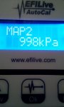
I verified this scale change on the bench using a Potentiometer‎ connected to ECM 5V-ref, low-ref and MAP sensor pins, then reading with EFIlive. You could do the same using the connector on a engine.


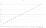
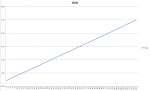
Below pics of 10 BAR scale bench testing

attachment.php


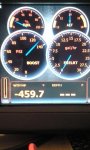
Corrected Boost - 10 BAR Setting On Lowrance Display

attachment.php


--

That's all ya need. This mod should also increase the max boost values reading on the Edge CTS.

Special thanks to Brayden Fleece for hacking through a 12628594 bin file to find us this scaling data.

Also thanks to DAVe3283 for modifying our original cax files for DSP5 and setting some limits. Please verify your scaling values before saving, as we have not tested these limit with erroneous data effects on the ECM.

Cheers

-K
 

Attachments

  • 20160422_175214.jpg
    20160422_175214.jpg
    171.8 KB · Views: 412
  • 20160422_175011.jpg
    20160422_175011.jpg
    161.8 KB · Views: 410
  • map-pin.jpg
    map-pin.jpg
    46.8 KB · Views: 412
  • lmm-map.zip
    2.2 KB · Views: 63
  • stock-map-scale-lmm.jpg
    stock-map-scale-lmm.jpg
    108.9 KB · Views: 418
  • 20160414_164845.jpg
    20160414_164845.jpg
    98.2 KB · Views: 400
  • 20160414_165531.jpg
    20160414_165531.jpg
    159.9 KB · Views: 398

Ridin'GMC

I like red
May 20, 2010
614
5
18
MA
So if you're maxing out the sensor, does this affect the tuning wise? By using the sensor that reads a higher value, is it going to help the ecm read correctly and adjust the fueling and timing to make it more efficient power wise?
 

kidturbo

Piston Tester
Jul 21, 2010
2,319
1,081
113
Somewhere On The Ohio
www.marinemods.us
By default the max table limits in the LMM OS set by EFIlive are 400kpa. I attempted to override these before and after changing the map scaling, but it knocked my changes back down to 400kpa.

If the stock sensor is actually 3.5 BAR as I've read, then it would only read 350kpa or 50psi out of the 400kpa or 58psi a tune could use. Take 50 and subtract 14.5psi for barometric pressure leaves it maxed out at 35.5psi corrected boost. By only changing the MAP to a 5 or 10 BAR and rescaling it, you gain 8psi or so of resolution.

Now if we could up the B2226 [Maximum Desired Boost] HARD table limit in EFIlive, that could open up the tuning resolution to match the new senors scaling. Someone might bring that up on the EFIlive forum and see what they say. Or search the LB7/LLY topic here on MAP scaling. Maybe it's easy...
 
Last edited:

duratothemax

<--- slippery roads
Aug 28, 2006
7,139
10
0
Wyoming
Great job with this!!

Sorry I sorta fell off the radar Ken....been totally SWAMPED with other (less exciting) projects and work. :( :mad: Its awesome to see what you've done so far with this.

I forget if we discussed this before...but is there any reason you chose to run an LMM OS and not an LBZ OS?
 

kidturbo

Piston Tester
Jul 21, 2010
2,319
1,081
113
Somewhere On The Ohio
www.marinemods.us
Yeah couple reasons, first and foremost I like the LMM OS better, plus way more of those ECM's are out there. Is the trucks I had available here to test on first.

Also that GMLAN high speed canbus ArbID's we were sorting out together are actually different between LBZ and LMM. I caught that while I had both ECM's here on the bench. Noticed the LBZ wouldn't talk to my gateways. Not the same ID's as we found.

Last the LMM OS has 2x factory 5V EGT probe inputs, which I discovered remain active even if you write out the DPF operations in the tune. So those sensors could be relocated from downstream to the manifolds and used with any digital display data. There was something else important to my marine builds different about them that I'm forgetting right off...

Guessing now that we've located the MAP scale values in a LMM OS, Brayden, Dave or I could likely isolate that same data position in the LBZ OS pretty quickly if someone needed it.

-K
 

duratothemax

<--- slippery roads
Aug 28, 2006
7,139
10
0
Wyoming
Yeah couple reasons, first and foremost I like the LMM OS better, plus way more of those ECM's are out there. Is the trucks I had available here to test on first.

Also that GMLAN high speed canbus ArbID's we were sorting out together are actually different between LBZ and LMM. I caught that while I had both ECM's here on the bench. Noticed the LBZ wouldn't talk to my gateways. Not the same ID's as we found.

Last the LMM OS has 2x factory 5V EGT probe inputs, which I discovered remain active even if you write out the DPF operations in the tune. So those sensors could be relocated from downstream to the manifolds and used with any digital display data. There was something else important to my marine builds different about them that I'm forgetting right off...

Guessing now that we've located the MAP scale values in a LMM OS, Brayden, Dave or I could likely isolate that same data position in the LBZ OS pretty quickly if someone needed it.

-K

Yup, good call on the EGT sensor inputs.

I did find this though: https://forum.efilive.com/showthread.php?24237-LBZ-ECM-amp-LMM-EGT-sensors&highlight=dave+EGT+LBZ

I emailed you a bunch of stuff that should be able to get you going on crank request via GMLAN. :thumb: :)

Ben
 

kidturbo

Piston Tester
Jul 21, 2010
2,319
1,081
113
Somewhere On The Ohio
www.marinemods.us
From what I've seen there is no good hardware reason you couldn't mod these ECM's to do what ever ya want. We attempted to load a LMM OS on a LBZ ECM using tech II one night for chitz and giggles. It started to take the firmware then crashed at like 20%...

We were amazed that it even started loading, and thought we had something, till it kicked and bricked.. Recovered it with a stock LBZ load. I'm pretty certain it would work with JTag-KTag tool, which I'm buying next week.. I know from bench testing you can't kil them, cause I tried several times.
 

duratothemax

<--- slippery roads
Aug 28, 2006
7,139
10
0
Wyoming
From what I've seen there is no good hardware reason you couldn't mod these ECM's to do what ever ya want. We attempted to load a LMM OS on a LBZ ECM using tech II one night for chitz and giggles. It started to take the firmware then crashed at like 20%...

We were amazed that it even started loading, and thought we had something, till it kicked and bricked.. Recovered it with a stock LBZ load. I'm pretty certain it would work with JTag-KTag tool, which I'm buying next week.. I know from bench testing you can't kil them, cause I tried several times.

The LBZ and LMM have slightly different CPU's (or cores, Im not sure...SOMETHING is different).

LBZ ECM is Bosch EDC16-C37
LMM ECM is Bosch EDC16-C42

You definitely cannot load/run an LMM OS into an LBZ ECM and vice versa....

Ben
 

x MadMAX DIESEL

<<<< No Horsepower
Dec 30, 2008
7,535
1
38
33
Lexington, Ky
That would be awesome if they had lbz map scaling! I bought a freaking stand alone data logging tool because we can't log past 37 psi. So annoying


Sent from my iPhone using Tapatalk
 

N2BRK

Well-known member
Dec 31, 2009
1,901
217
63
This got WAY too long. Sorry in advance to those that make it to the end, but THANK YOU!!!

I thought I'd chime in with some answers to make this more simple for people trying to do this upgrade, but I'm afraid that I have more questions than answers.

The LMM cax file allows you to only plot two coordinate pairs. One at 1.564vdc and one at 5vdc. This leaves me with two problems. One is that the sensor won't reach 5v output, so I have to predict what it might be at 5v... which leads to the second problem - it is not a linear result when you plot the output data from the sensor!

I should mention I'm running the Honeywell MLH100PLG06A 100psi sensor that McRat recommended back in '09. I made a little harness and fed it 4.8vdc from an old cell phone charger. I observed the following in PSIG:
V/PSI
.42,0
.84,11
1.33,24
1.42,26.5
1.47,28
1.55,30
1.58,31
1.62,31.5
3.86, 91
4.22,100
4.5,107.5
4.68,112
Then 4.7v at every pressure above 120psi until my little benchtop compressor maxed over 130psi

If I take plot points and try to create the old 6th grade y=mx+b for a slope... it keeps changing based on which points I choose - so it isn't linear.

For example, if I choose .84v,11psi and 4.5v,107.5psi I get 5v=120.6683psi. Which I already observed is wrong. So if I take .84v,11psi and 4.7v,120psi then I get 5v=128.473psi.

ASSUming that the last formula that I used is the closest for predicting 5v, then my plan is to enter the following:

I'll use the observed value of 30psi for 1.564v
I'll use the predicted value of 128.473psi for 5v

Has anyone else used results like mine, fine tuned this, or can tell me I'm all f'd up - I'm asking to learn and maybe help others. I have no ego in this - I'm spent. LOL

Thanks,
Wally
 

2004LB7

Well-known member
Dec 15, 2010
6,363
1,732
113
Norcal
This got WAY too long. Sorry in advance to those that make it to the end, but THANK YOU!!!

I thought I'd chime in with some answers to make this more simple for people trying to do this upgrade, but I'm afraid that I have more questions than answers.

The LMM cax file allows you to only plot two coordinate pairs. One at 1.564vdc and one at 5vdc. This leaves me with two problems. One is that the sensor won't reach 5v output, so I have to predict what it might be at 5v... which leads to the second problem - it is not a linear result when you plot the output data from the sensor!

I should mention I'm running the Honeywell MLH100PLG06A 100psi sensor that McRat recommended back in '09. I made a little harness and fed it 4.8vdc from an old cell phone charger. I observed the following in PSIG:
V/PSI
.42,0
.84,11
1.33,24
1.42,26.5
1.47,28
1.55,30
1.58,31
1.62,31.5
3.86, 91
4.22,100
4.5,107.5
4.68,112
Then 4.7v at every pressure above 120psi until my little benchtop compressor maxed over 130psi

If I take plot points and try to create the old 6th grade y=mx+b for a slope... it keeps changing based on which points I choose - so it isn't linear.

For example, if I choose .84v,11psi and 4.5v,107.5psi I get 5v=120.6683psi. Which I already observed is wrong. So if I take .84v,11psi and 4.7v,120psi then I get 5v=128.473psi.

ASSUming that the last formula that I used is the closest for predicting 5v, then my plan is to enter the following:

I'll use the observed value of 30psi for 1.564v
I'll use the predicted value of 128.473psi for 5v

Has anyone else used results like mine, fine tuned this, or can tell me I'm all f'd up - I'm asking to learn and maybe help others. I have no ego in this - I'm spent. LOL

Thanks,
Wally

Looks pretty darn linear to me
 

Attachments

  • MAP Scaling.png
    MAP Scaling.png
    13.4 KB · Views: 39
  • MAP Scailing.zip
    20.5 KB · Views: 11

N2BRK

Well-known member
Dec 31, 2009
1,901
217
63
Your graph never hits 5v. What slope did you use? If I take two data points at different samples I’ve observed, I get different slopes. PSA - I’m great with math if I can use my toes. Geometry isn’t my forte. Lol
 

2004LB7

Well-known member
Dec 15, 2010
6,363
1,732
113
Norcal
here it is extended out to 5 volts. it may not be right but it is based on your numbers you put up so....???. part of the issue may be testing it at 4.8 volts instead of 5 volts. maybe not
 

Attachments

  • MAP Scailing 2.zip
    19.4 KB · Views: 7
  • MAP Scaling 2.png
    MAP Scaling 2.png
    11.9 KB · Views: 33

N2BRK

Well-known member
Dec 31, 2009
1,901
217
63
Sorry if I’m just missing something obvious, but this isn’t helping to answer the question of how to predict 5v. The cax file needs a value at 5v entered. The sensor will never show 5v and depending on where I take my sample on that graph, I’ll get different results. My truck won’t see over 46psig anyway, so maybe it won’t make much difference which figure I chose, but for accuracy I’m looking for best guesstimate. At least to start. Maybe have to log back to back with stock after I get close enough to make it run :)
 

N2BRK

Well-known member
Dec 31, 2009
1,901
217
63
Ok I see you used 5v=120psi. I’ve already observed 120psi at 4.7v. That’s why I was planning to guesstimate higher. The 4.8 was within spec for the gauge, but yeah it’s not a full 5. I could redo under power from the truck. I bought an extension harness to hack up. :)
 

N2BRK

Well-known member
Dec 31, 2009
1,901
217
63
That’s what I used but it was for an old flip phone and only 4.8vdc. I’ll re-do at 5vdc. With the setup I made it’s pretty easy to make readings. Thanks