"Whats inside".....Allison 4th gen TCM

duratothemax

<--- slippery roads
Aug 28, 2006
7,139
10
0
Wyoming
Im going to start a new little discussion segment/forum in my vendor section on Duramax Diesels.

As everyone knows, I get a kick out of electronics and whiz-bang little gadgets that are related to trucks/automotive stuff. I think it really interesting the electrical engineering, electronics design, and computer technology that goes into the simplest of things in cars/trucks nowadays.

I like explaining things, I like figuring out how things work, and I like sharing my knowledge about things that interest me. So I figured I would start a series of threads where Ill take something apart, maybe describe a little bit about whats going on, and if anyone has questions, Ill try to answer them. Im just a stupid dumbass liberal-arts major; Im not a formally-educated electrical engineer or computer-science engineer so Im not going to have all the answers....but Ill at least have some pretty high-resolution pictures for you guys to look at.

Its going to be creatively called the...wait for it..."whats inside" segment.

OK. Here we go.

For starters, the thing was designed to be assembled once and never taken apart. It is sealed/glued together. I had to spend a few minutes looking over it just to figure out HOW to open it. The only reason I took this one apart was because it was dead. Not "dead" as in it was flashed wrong and now nothing will communicate with it...but actually physically damaged internally...There is an internal short somewhere in the power supply or ground circuit because when plugged in, it doesnt even draw any current.

So I pried it open.

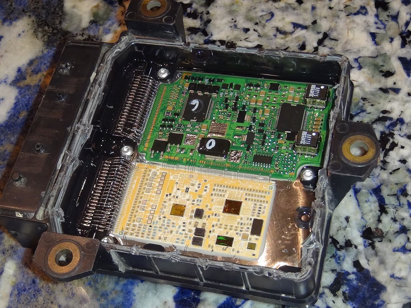
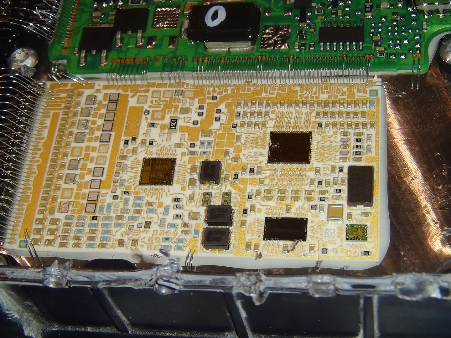
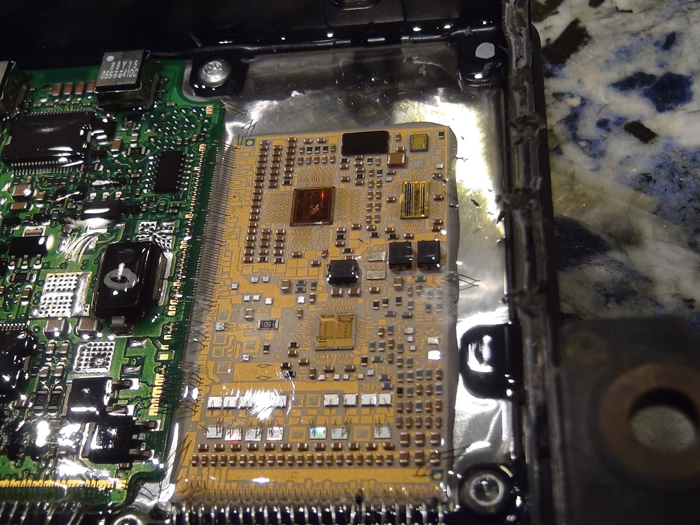
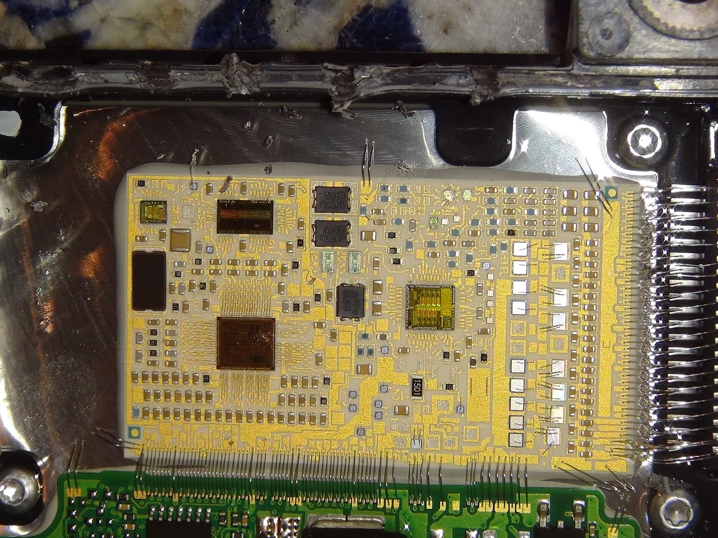
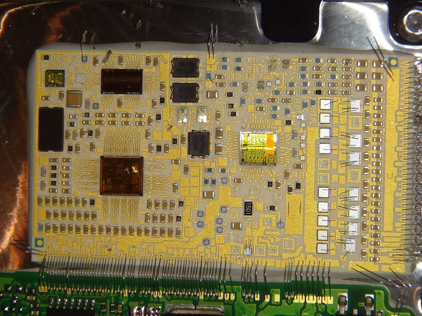
The whole PCB (printed circuit board) is potted. What that means is its fully encased in a sort of epoxy to keep it 100% liquid and air sealed...and to protect against vibration. The potting stuff allison used is something like a mixture of jello and rubber cement. Its squishy but not sticky, and its not hard. Some sort of gel, I dunno.

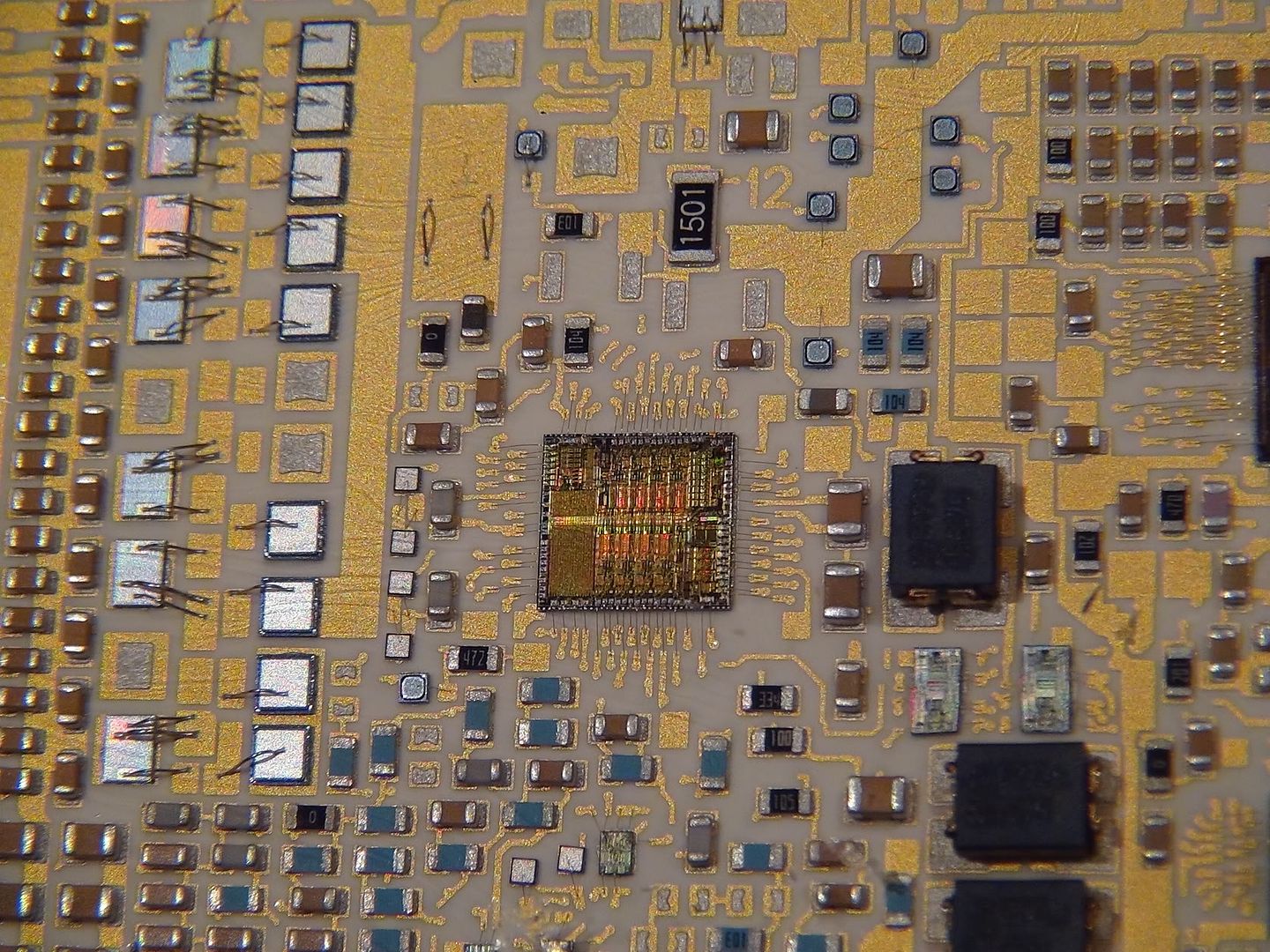
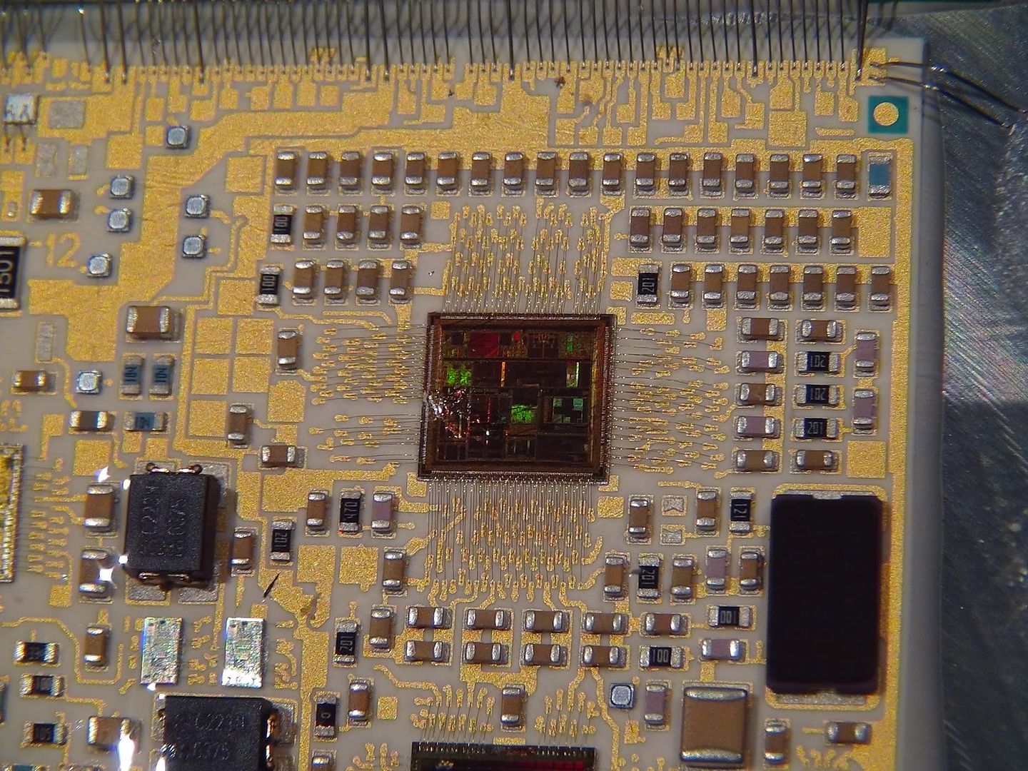
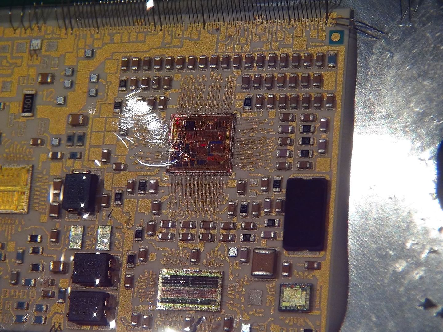
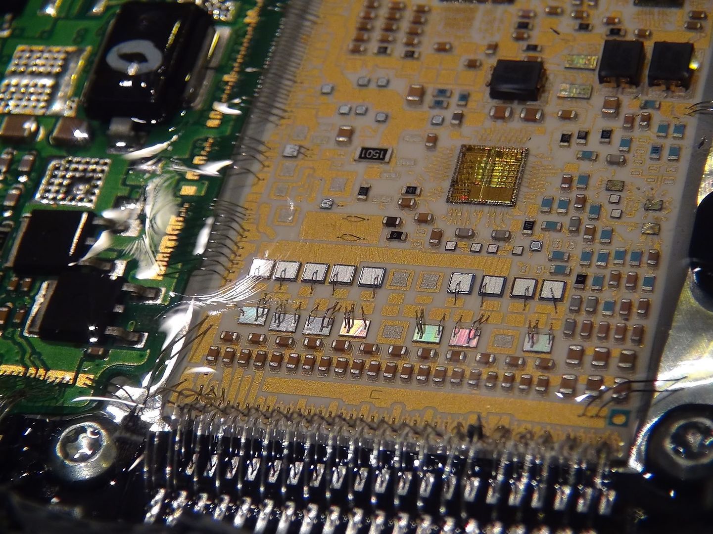
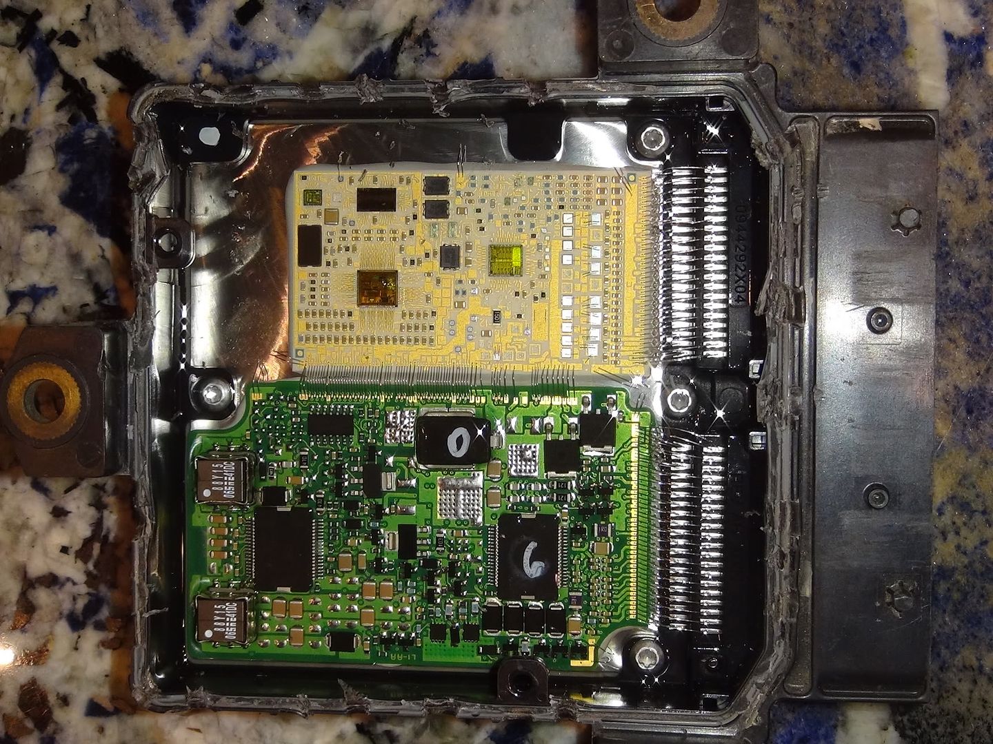
You can see the tiny wires that connect the two boards together...these wires are "floating"/suspended in the gel potting compound. They are incredibly small and delicate. Both PCB's are mounted solidly to the big heat sink, which has the spiky fins on the other side that we can see on the outside.

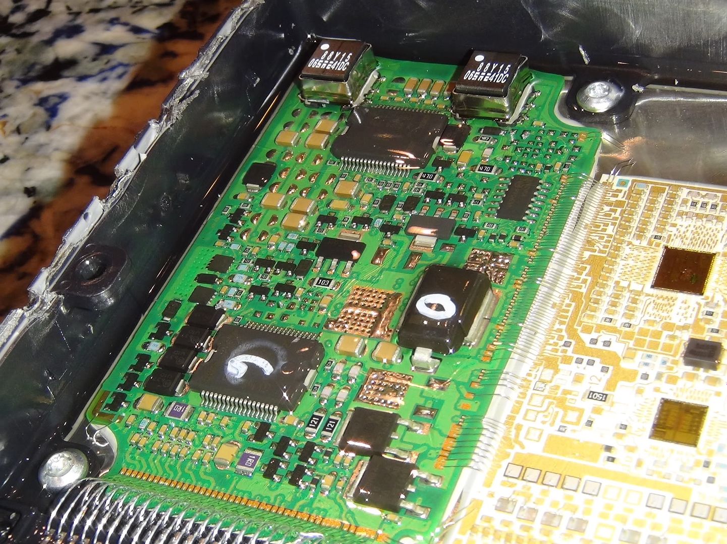
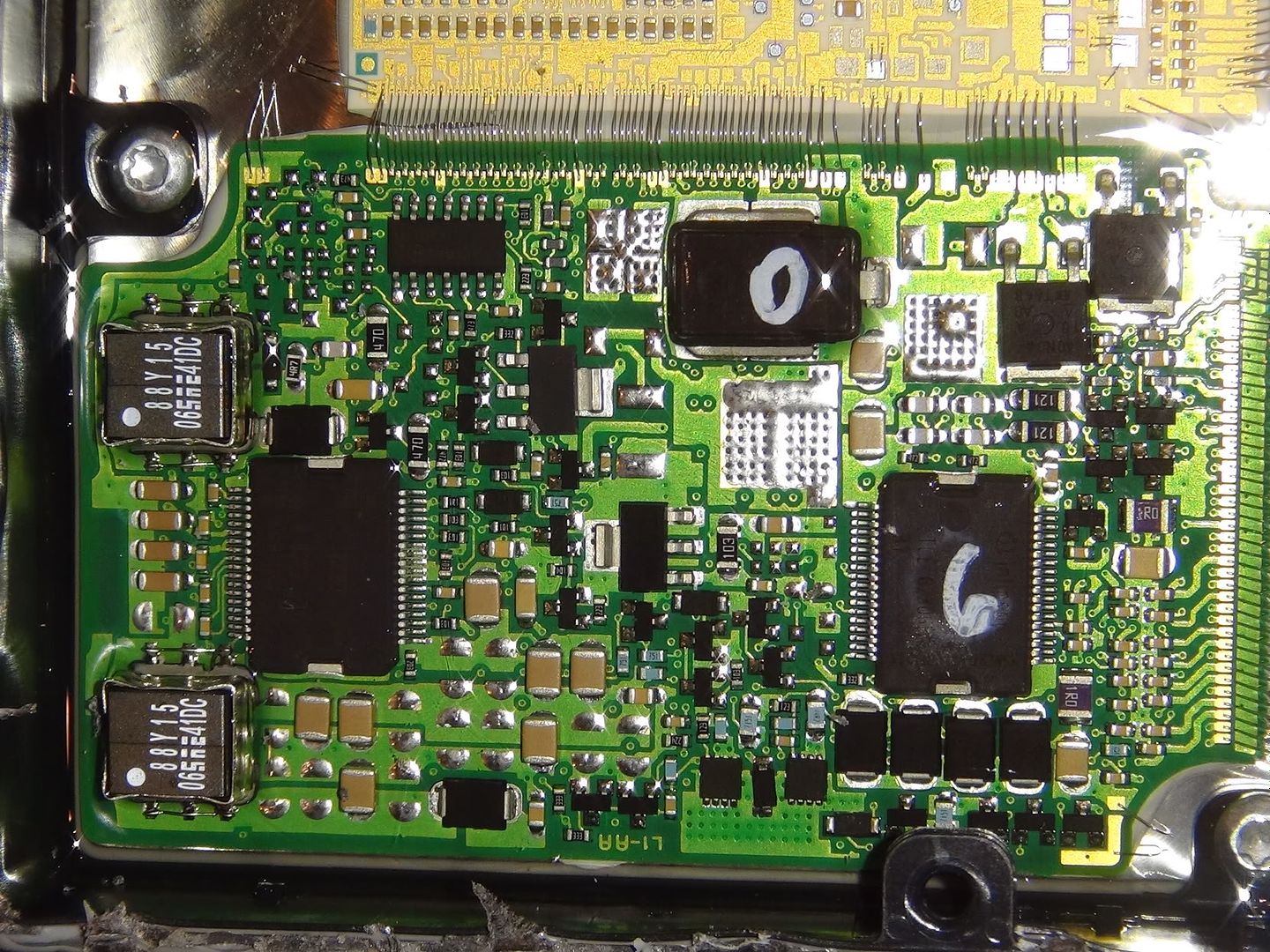
Its divided up into two separate boards. One is the controls and the other is the drivers. Basically one side is the brains and the other is the muscle (to drive the solenoids and stuff). The green PCB is the driver board.

Later, ill make some diagrams pointing to various objects and what [I think] they are. Fingers will probably be able to make more sense of this than me, but I still find it cool to look at just the same. :)

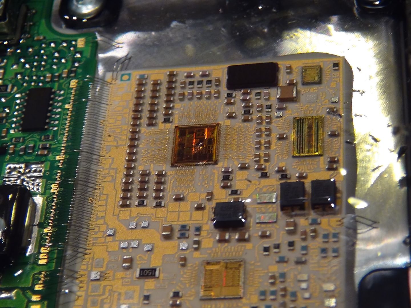
The processor cores on the tan/brown board are exposed, as you can see. They are holographic-looking things and when you tilt the TCM side to side, they change color and look 3D..very cool.

the pictures are big so you can really look up close. Even if you arent an electronics person, its still interesting to see the detail and how small/detailed some of the stuff is.

DSC00143.jpg

DSC00142.jpg

DSC00141.jpg

DSC00140.jpg

DSC00139.jpg

DSC00138.jpg

DSC00137.jpg

DSC00136.jpg

DSC00135.jpg

DSC00134.jpg

DSC00133.jpg

DSC00132.jpg

DSC00131.jpg
 

MACKIN

Smell My Finger...
Aug 14, 2006
3,948
1
0
Connecticut
I bet when Ben got it open it was pure euphoria and all the blood rushed out of his big head to his little head and he probably blacked out for a minute or two he was so excited!

I wonder which was more exciting:

1) Getting his Cherry Popped !
2) Cracking Open a Forth Generation GM Allison TCM! :roflmao:
 

duratothemax

<--- slippery roads
Aug 28, 2006
7,139
10
0
Wyoming
I bet when Ben got it open it was pure euphoria and all the blood rushed out of his big head to his little head and he probably blacked out for a minute or two he was so excited!

I wonder which was more exciting:

1) Getting his Cherry Popped !
2) Cracking Open a Forth Generation GM Allison TCM! :roflmao:

wouldnt you like to know. :roflmao:
 

duramax hd

Member
Feb 27, 2009
664
0
16
36
CT
Hey Mack, I found out a few weeks ago my cousin and her boyfriends went to school with Ben...They also told me some veryyyy interesting stories about him! Ben, Id like to put my truck back together, so if you dont call me back I will be forced to go public with these :roflmao:
 

z79outlaw

New member
Apr 20, 2007
793
0
0
37
Salem WI
Hey Mack, I found out a few weeks ago my cousin and her boyfriends went to school with Ben...They also told me some veryyyy interesting stories about him! Ben, Id like to put my truck back together, so if you dont call me back I will be forced to go public with these :roflmao:

Is the guy to girl ratio that out of whack in CT? That shit is not cool, must make for some weird get togethers...
 

Fingers

Village Idiot
Vendor/Sponsor
Apr 1, 2008
1,713
84
48
White Oak, PA
The Back side of both boards are also populated with components.

You don't often see de-cased chips. And this controller has three. Processor, Com, and memory.
 

DAVe3283

Heavy & Slow
Sep 3, 2009
3,681
236
63
Boise, ID, USA
The Back side of both boards are also populated with components.

You don't often see de-cased chips. And this controller has three. Processor, Com, and memory.
I work for Micron, and we're starting to sell more and more of our product as die on board (not cased). Of course, it is usually going into cell phones where space is more of a premium than in here. It is interesting they went with die on board. It looks like the whole thing was assembled in a clean room (not cheap).

Also, looking at it, I think there are drivers on both boards, not just the green board. I could be wrong though, as we're only seeing the top of the boards.
 

Fingers

Village Idiot
Vendor/Sponsor
Apr 1, 2008
1,713
84
48
White Oak, PA
Die on Board is used for space and heat dissipation.

Speaking of which, I don't see any thermal sinks or traces on the processor board. Not driving much other than signals. Even those look to be clamped and isolated.
Now the drive board appears to be driving a fair bit. Note the pin cushion areas. Those are for either hi heat or noise reduction. Considering we can see some drivers soldered to them on this side. Chances are good there is another one the other side of the open pin cushion areas.

Now that I have looked a little closer I see there are several more Die on Board components than I thought. Two I recognize as dual OP-Amps.
 

TheBac

Why do I keep doing this?
Staff member
Apr 19, 2008
15,318
1,605
113
Mid Michigan
...and to think, that TCM probably has more computing power than what took the astronauts to the moon and back. Pretty amazing all the computing power packed into that small case.
 

duratothemax

<--- slippery roads
Aug 28, 2006
7,139
10
0
Wyoming
...and to think, that TCM probably has more computing power than what took the astronauts to the moon and back. Pretty amazing all the computing power packed into that small case.

many hundreds of times more computing power. If not, thousands?

Even the microcontrollers/computers that I use in my lockup controllers are several times more powerful than the Apollo 11 guidance computer...
 

paint94979

Beer Nazi
Sep 18, 2006
11,714
7
38
37
...and to think, that TCM probably has more computing power than what took the astronauts to the moon and back. Pretty amazing all the computing power packed into that small case.

are we really sure the Apollo 11 mission even landed on the moon :D ???
 

DAVe3283

Heavy & Slow
Sep 3, 2009
3,681
236
63
Boise, ID, USA
Die on Board is used for space and heat dissipation.

Speaking of which, I don't see any thermal sinks or traces on the processor board. Not driving much other than signals. Even those look to be clamped and isolated.
True, they are not driving much. However, look at the row of 7 dies closest to the connector (not the bus between boards). Those look very much like FETs to me, and have fairly thick bond wires, as well as moderate pad sizes. The proximity to the connector and bypass caps would indicate these are driving something external to the TCM, at reasonable power levels. Nothing like the drive board.
Now the drive board appears to be driving a fair bit. Note the pin cushion areas. Those are for either hi heat or noise reduction. Considering we can see some drivers soldered to them on this side. Chances are good there is another one the other side of the open pin cushion areas.
Yes, this board is sourcing/sinking a lot of current. Lots of heavily heat-sinked transistors and diodes down near the external connector. I would guess these are what run most of the solenoids in the transmission.

I see what appear to be two large magnetics at the far edge of the board (labeled 88Y15) surrounded by smoothing caps and reasonably large diodes. These appear to be DC-DC converters, probably buck converters. I would guess the small one (near the common bus) is to provided a reference 5V for sensors. Not sure what the larger one is for, unless they are favoring variable DC voltage over PWM for certain solenoids? It looks like it can push a lot of current.

Now that I have looked a little closer I see there are several more Die on Board components than I thought. Two I recognize as dual OP-Amps.
I see what appears to be a general purpose micro, some memory (RAM or Flash, can't tell from the phots), and a more specialized micro (DSP or FPGA?). There really are a lot more, but that clear potting compound makes them hard to see. The ones that have me stumped are all the squares with the squircles (yes, that's a real thing, apparently) inside, and the small bond wire to the squircle on top.

I wouldn't mind getting that TCM under a scope for the fun of it. Or Ben, want to see if you can find something that safely dissolves the potting compound so we can get some better photos? Though the photos you got are remarkably good considering it is through the compound. Thanks for sharing them! :woott:
 

Fingers

Village Idiot
Vendor/Sponsor
Apr 1, 2008
1,713
84
48
White Oak, PA
I see what appears to be a general purpose micro, some memory (RAM or Flash, can't tell from the phots), and a more specialized micro (DSP or FPGA?). There really are a lot more, but that clear potting compound makes them hard to see. The ones that have me stumped are all the squares with the squircles (yes, that's a real thing, apparently) inside, and the small bond wire to the squircle on top.

Those are ferrite core inductors.

Pure square with a single center tap is probably a Cap, maybe a resistor.

The Three wire device has me a little stumped. I suspect it is an isolator of some sort.
 

duratothemax

<--- slippery roads
Aug 28, 2006
7,139
10
0
Wyoming
The 5-speed TCM simply feeds all of the solenoids with a +12v source that is simply "tapped into" the +12v ignition circuit feeding the TCM. The "12v reference wires" going to the solenoids from the TCM are just internally spliced into +12v ign. And then the TCM provides the "control" via an internal low-side driver. The only solenoids that actually get a dedicated high-side driver are the two trim solenoids, because they are PPC solenoids. (more on that below).

Whereas the 6-speed TCM actually has both high side AND low side drivers to control ALL of the solenoids. The high-side drivers dont really do anything; they basically just supply +12v all the time and the low-side drivers to all of the work. The high-side drivers are just cycled on/off for 6 seconds at each startup/ignition cycle to check the integrity of the drivers and the solenoids/transmission harness wiring. Then, otherwise the high-side drivers just stay energized all the time.

I dont know why Allison did this (there was nothing wrong with just feeding the solenoids straight +12v ign power); probably just for better/more accurate circuit diagnostics...so the TCM can actually isolate and control ALL of the wiring going to the solenoids. And with an actual monitored high-side driver, you the TCM can monitor the circuits for both shorts to +12v and shorts to ground, and open circuits on BOTH sides.

And, the TCC solenoid on the 6-speed is not a standard PWM solenoid. Its a PPC (pressure proportionate to current) solenoid, so the TCM has to precisely monitor and control not only the PWM of the control circuit, but how much current is flowing through the TCC solenoid circuit.

Whereas the way the 5-speed TCM is wired/the way the solenoids are controlled (with the exception of trim a/b), the TCM can basically only run diagnostics on the "control" (low-side) side of the circuit.

I assume those two big square things are the two high-side drivers. They have to source a decent amount of current. The TCC solenoid alone can draw up to 2 amps or so.
 

McRat

Diesel Hotrodder
Aug 2, 2006
11,249
26
38
64
Norco CA
www.mcratracing.com
...and to think, that TCM probably has more computing power than what took the astronauts to the moon and back. Pretty amazing all the computing power packed into that small case.

I used to have a Core Memory board like what was used for Apollo. This is what I remember (damn, I should have kept it):

It was 1,024 little donut magnets with 3 wires running through each one. It was about 10x10"? and cost over $1000 when new. It held 1024 bits of data, or 128 bytes.

To get as much RAM as is in my phone, would cost about $2 trillion dollars in 1969 currency, and would probably cover 67 square miles?

Dunno. Things change.
 

duratothemax

<--- slippery roads
Aug 28, 2006
7,139
10
0
Wyoming
I used to have a Core Memory board like what was used for Apollo. This is what I remember (damn, I should have kept it):

It was 1,024 little donut magnets with 3 wires running through each one. It was about 10x10"? and cost over $1000 when new. It held 1024 bits of data, or 128 bytes.

To get as much RAM as is in my phone, would cost about $2 trillion dollars in 1969 currency, and would probably cover 67 square miles?

Dunno. Things change.

yep! core rope memory. Ferrite magnets with wire going through them arranged into various strands, "coded" by hand.