T87 Swaps

kidturbo

Piston Tester
Jul 21, 2010
2,320
1,082
113
Somewhere On The Ohio
www.marinemods.us
I'm back on the T14 swap this week. I've been working on the house, doing some remodeling, and a new roof. Went all metal roofing and love it. However the house didn't, so it gave me the shingles... Was a pretty itchy couple of weeks.

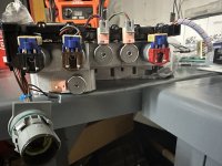
All recovered now, and safe to be around non-chickenpox-vacinated children again.. So, I started digging out all the hardware to put a couple of harnesses together this week for those waiting. Have most of the valve body components now. Then curiously realized by robbing the wire covers off the factory T14 connector, and snapping those onto my male 80 pin adapter, I can also build an Allision TCM relocation / extension cable..

Now why anyone would want such a cable when we are all trying to upgrade from the T14 TCM, I have no idea. But I snapped a few pics that look cool and gonna go post em on Facebook to see if I get any bites...

For our main use, I do like the seal, wire guide, and cover options this adapter block design provides. However, i got a bit anxious test fitting and snapped a couple of the locking pins off one side. So, I have to address that in the 3D resin options and hopefully get closer to injection molding strength. But it's close..


05d43e1a1bfa6d7d3bd40c06fa68191e.jpg
5441902347e865b1c7ebbedd7d40cf82.jpg
f1ca12692448fa1195ce044e54967997.jpg
f3bb1913cc229ad1afb94d10b02fa96c.jpg
611d9c0ad6fb4fffbd27312b8e124aff.jpg


Sent from my SM-S901U using Tapatalk
 

kidturbo

Piston Tester
Jul 21, 2010
2,320
1,082
113
Somewhere On The Ohio
www.marinemods.us
Ok, curiosity got the best of me, and I exercised the T87 PCB from its aluminum case...

Took an hour to figure out how they put these together. Heatsink pattern is glued to the case with the same seam sealer grade goo that holds the rear case cover on. And the 60pin connector is a 2 piece design that was superglued together at assembly. In short, they never intended for it to come apart.. But some heat and an oscillating cutter changed its mind..

I found most of what I was originally digging for, so I don't mind making this unit a lab rat. And first interesting part is they used a cap and "3" 240ohm 1/4w resistors in Paralell pulled to ground on each input speed sensor.. Why are they wasting all this power sending a 9v ref out, then heavily knocking that down with stack of resistors before processing at a 3.2v MPU inputs.?? But this explains why the typical VR to 5v Square wave converter was being rejected, it's basically a short to ground by design.

We shall explore more, so here is some pics of both sides of what looks to be a 3 or 4 layer board.

bf65c2a4c0ed4411affa345b8d913249.jpg
f608ae3e2545d3063cdb4299b5804a7e.jpg
2ef8116f817da2741970f49abba58298.jpg


Sent from my SM-S901U using Tapatalk
 
Last edited:

kidturbo

Piston Tester
Jul 21, 2010
2,320
1,082
113
Somewhere On The Ohio
www.marinemods.us
Picked up a couple of these nifty workbench PCB holders. Now it can't run away while I drag test leads across all these shiny spots to see if it screams...

HA HA HA HA :devilish:

20240422_215321.jpg


Maybe I should first see if it still works, after hacking it outa the case..
 

kidturbo

Piston Tester
Jul 21, 2010
2,320
1,082
113
Somewhere On The Ohio
www.marinemods.us
Also ordered some high wattage 5ohm resistors to try and replicate the valve body solenoids on the bench. However once did the math, went back ordered some bigger 50W versions with heat sinks. My estimate at 13v is like 35 watts per unit. So we'll test that shortly.

c5bf39965e823d0e44340af0e3d40b06.jpg


Sent from my SM-S901U using Tapatalk
 

Cougar281

Well-known member
Sep 11, 2006
1,754
213
63
St Louis, MO
If it ain't happy, we'll know it's not wrong resistance..


2d03871e3cc49e4da9ad6bef52c309a0.jpg
5f245fbf81f37b51560a8176b7e7f0c4.jpg


Sent from my SM-S901U using Tapatalk
We'll see how that works... I put a resistor in l parallel with the solenoid in my truck so it brought the resistance down to ~5 ohms, and the DTC changed from an incorrect resistance code to an incorrect current code. 🤦‍♂️
 

2004LB7

Well-known member
Dec 15, 2010
6,372
1,733
113
Norcal
We'll see how that works... I put a resistor in l parallel with the solenoid in my truck so it brought the resistance down to ~5 ohms, and the DTC changed from an incorrect resistance code to an incorrect current code. 🤦‍♂️
You have to remember that coils/solenoids/inductors respond very differently from a purely resistive loads. Especially on a PWM or A/C waveform.

Without knowing the coding used to determine the health of the coils it's a guessing game as to tricking it
 

kidturbo

Piston Tester
Jul 21, 2010
2,320
1,082
113
Somewhere On The Ohio
www.marinemods.us
Yeah, I forgot that aspect of it. If these new bad boys don't cut it, I'll have to go dig in my buddies' transmission pile to find the rest. Have the T14 harness checked out and ready to go. Guess we'll see if it likes em or not first..

b3a919e182b8a994db8d63f3148c094b.jpg
c6b07e07829de0c290a9721d61c7b981.jpg


Sent from my SM-S901U using Tapatalk
 

kidturbo

Piston Tester
Jul 21, 2010
2,320
1,082
113
Somewhere On The Ohio
www.marinemods.us
Got one wired up, and it runs a bit cooler than an actual solenoid. Which will burn the outa your hand after 5 minutes on time.

But my loaner T14 seems to me a bit flaky after five minutes or so running. Stopped communicating on me.
ad0feb0ef9bd3e24bbf0ee7595489267.jpg


Sent from my SM-S901U using Tapatalk
 

kidturbo

Piston Tester
Jul 21, 2010
2,320
1,082
113
Somewhere On The Ohio
www.marinemods.us
Ok,, so far for this T14 is a happy camper with 4 of these bigass hot plate resistors and 4 stock solenoids. I also put some little 12v rated LED lights on em, so we can see which valve is active.. That all seems to work, I've limp stuck it in 3rd half dozen times already... I also checked the PWM on those HOT against an actual solenoid open, and see a slight difference. So guess we'll see on the T87..

This T14 seems to be stable enough to know whats going on in the world and reports data ok. Let it run a few times 5 minutes or more. Charging up my bench battery, was down to 9v earlier. While the VIN is still all 4@948#(#(Y%8, it did let me read the tune file out. Has a single 701 code showing before adding any RPM signal. But I don't have a pressure manifold connected yet. So guessing it's ok internally.

What was the last known state of this one @pl_silverado ? Besides aerated case.

A50-Read-Issues.jpg

About the pressure manifold. That's the other part I am missing. But my plan was to link the pressure switches to our solenoids via some mosfets, [got a whole bunch of extras] so when it shifts, it sees the proper pressure switch signal active. Hoping that will keep it happy. However, I could use a hand mapping that out on the Hydraulics to Electronics conversion side.. No idea how the plumbing works.. In other words, a little help please.. LOL

Pressure-Switch-Manifold-Pinout.jpg
 

kidturbo

Piston Tester
Jul 21, 2010
2,320
1,082
113
Somewhere On The Ohio
www.marinemods.us
Ok got a few things sorted out from our factory 09 LMM / A50-6spd setup. First, did anyone ever notice they put two of the exact same 6 pin connectors in the valve body harness?? This range switch works much better when connected to the correct one.. Next someone will tell me those solenoids belong in specific positions... :unsure:

20240425_070500.jpg

Ok, onto the fun stuff.

I tested the 2 biggest questions I had for our pre-LML year related swaps. First was the P/N indicator, which is hard wired straight outa the valebody harness to the ECM, and never touches our our 80-Pin T14 connector. Goes straight to the X2 connector, and enables our Starter Relay Control on pin X1 71. That's good I guess, since we need not be concerned about it in our swap hardware or software. While I believe this can be ECM switched to use CANbus data rather than the hard wired pin, would only be an issue if you swap to a 8 or 10spd transmission. So I wired it up like factory, ECM and TCM both happy, and we'll roll with it for now..

P-N_Line.jpg

ECM_TCM_P-N_Pins.jpg

ECM_TCM_P-N_Active.jpg

The second and must be addressed concern is the TCM emulated TOS or VSS signal. That one comes straight out of our 80 pin T14 connector, and runs to the ECM and other nodes. It also can be switched to use CANbus data I believe, and I will try and review those options tomorrow. But for now, I verified an actually lucky break I suspected. Our TOS line from the TCM sends out a 12v level square wave signal, and you guessed it, 40 pulse per revolution. Same as our new style output speed sensors, or exactly what our T87/A TCM requires.

So think we might try and pull the old preverbal kill two birds with one stone here. Since we need to convert the VR sytle speed sensor signals to a 9v square wave for our T87, we can possibly just tie Output Speed and TOS together and call it done. Worst case, add another mosfet to keep em separated.. First on the testing block this weekend.

20240425_045523.jpg

That's all for this episode.
 
  • Like
Reactions: pl_silverado

pl_silverado

Member
Jan 29, 2012
99
71
18
What was the last known state of this one @pl_silverado ? Besides aerated case.

View attachment 123209

Honestly I couldn’t tell you. It was in a truck I rebuilt, and threw up the shift inhibited after running for about 5 min so I replaced it after seeing the non factory vent hole. Figured someone swapped it before it made it to auction.

Cut it open and see what’s going on inside if you want. If you get jammed up I can send another out of one of the other trucks I have in progress.
 
  • Like
Reactions: kidturbo

pl_silverado

Member
Jan 29, 2012
99
71
18
Ok got a few things sorted out from our factory 09 LMM / A50-6spd setup. First, did anyone ever notice they put two of the exact same 6 pin connectors in the valve body harness?? This range switch works much better when connected to the correct one.. Next someone will tell me those solenoids belong in specific positions... :unsure:

They do have their specific positions. Black one is the a trim, first plug closest to the main connector / pressure switch, it’s normally closed. Brown one is b trim, which is next in line and it’s normally open. Then the two regular pink solenoids, followed by the red one.

I’ll see if I can find some pictures. Built 6 of these last month and I have to have taken at least one picture.

1714075785807.jpeg
 
  • Like
Reactions: kidturbo