Yeah seemed kinda odd to me why Molex would use a Yazaki terminal and seal but they are sister companies so best guess as to why.Ok thanks.. It was the Yazaki #7116-4152-02 had me wondering.
T87 Swaps
- Thread starter kidturbo
- Start date
You are using an out of date browser. It may not display this or other websites correctly.
You should upgrade or use an alternative browser.
You should upgrade or use an alternative browser.
Update on the A50 connector. Found a small issue with the pin choice my 3d modeling expert overbooked, until he got the terminal sockets part printed.. Wrong pitch pins, no fit the spacing..
Had to dig up a different terminal # and he's back on track again. Sometimes, it's the smallest things that matter the most..


P.S. I buying him a proper weatherpak crimp tool once he's done.. He death to terminals..
Had to dig up a different terminal # and he's back on track again. Sometimes, it's the smallest things that matter the most..


P.S. I buying him a proper weatherpak crimp tool once he's done.. He death to terminals..
33000-1004 is the molex mating terminal I’ve been using.Update on the A50 connector. Found a small issue with the pin choice my 3d modeling expert overbooked, until he got the terminal sockets part printed.. Wrong pitch pins, no fit the spacing..
Had to dig up a different terminal # and he's back on track again. Sometimes, it's the smallest things that matter the most..
P.S. I buying him a proper weatherpak crimp tool once he's done.. He death to terminals..
Yeah those are the correct part for OEM mat seal option. The latching is a bit more complex to "print" than some others. And while I found the correct wire separator off the female side, haven't been able to locate the mat seal with correct pitch, without buying the whole female connector assembly.. So for the first prototypes, wanted to go with a seal on wire design to keep the terminal cavity simple. Delphi / Metri-pak 12045773-L seems to fit, with about .5m between the seal cavity.33000-1004 is the molex mating terminal I’ve been using.
The first A40/A50/T14 to T87 test adapter harness. Only had two unexpected DTCs initially, one of which I figured out and resolved pretty quick, the other might be a little more difficult. In my quick drive up my street, things worked (or didn't work) in ways that I expected.
Attachments
Congrats on being first to control an Allison 1000 with a T87 TCM.
Now to make it a happy marriage..
Now to make it a happy marriage..
Yeah I can probably make the trip up that way on Monday.@kidturbo im going to be down in Logan on Monday 19th. If you want to get together and get some live data.
Sent from my SM-S901U using Tapatalk
Spent a few hours last week playing with these new style speed sensors, after @Cougar281 tested one of the VR converter with his T87 in the truck. While the T87 will accept a powered Arduino Uno pulse signal, it's pull down resistor on the sensor line doesn't work with these 5v VR converters. We have tested 2 boards based on the Maxx chip design.
With a new style sensor connected to T87, the line voltage reads 3v, being powered off the factory 9V supply from the TCM. However, if you read the output pin on the actual sensor when not connected to the TCM, it reads 8 volts. So there is some strange line levels in play.
My question is, what does everyone think about think about putting a mosfet on the speed sensor lines, fed by 9v Ref, and triggered by our 5v VR converter?
Here is line in, out, and resistance value of these new sensors.


Sent from my SM-S901U using Tapatalk
You might be able to use a solid state relay instead of a mosfet. Would be easier for a layman to wire in and probably more robust
Sounds like the resistance/impedance of the sensor is too high for the current the TCM wants. Is there another sensor with higher current output you can use?
Sounds like the resistance/impedance of the sensor is too high for the current the TCM wants. Is there another sensor with higher current output you can use?
The goal here is trying to emulate the 2016+ factory sensor, using this small pcb which converts VR sine wave sensor inputs to 5v hall effect outputs. While the output voltage is within range, this circuitry gets knocked down soon as ya connect it to the signal input lines on TCM.
Since we need a few more things on this signal converter, plan was to just print a custom board with all the required hardware including canbus.
Below is the staring 12v supply, sine to 5v square wave converter. This Maxx chip is the go to for all the aftermarket and open source ECM options. We just need a 9v version of this puppy. So any type of relay capable of switching 155,000 times per mile should do.


Sent from my SM-S901U using Tapatalk
Ken, can you get a variable resistor and hook it up as a voltage divider potentiometer and see at what point the sensor voltage drops below the TCM threshold? And also wire up the variable resistor as a rheostat and into the TCM being fed from your good PWM source to see at what resistance the voltage into the TCM starts to fall off. That can help us figure out what current the TCM needs and design around that.
I'm thinking a gate driver might be better then just a straight up mosfet. Would be less sensitive to errors and transient voltage. Knowing what the current that can be supplied before it falters or drips too low would be helpful in selecting a driver
I'm thinking a gate driver might be better then just a straight up mosfet. Would be less sensitive to errors and transient voltage. Knowing what the current that can be supplied before it falters or drips too low would be helpful in selecting a driver
The issue is, the output level of the Maxx chip is already below what the TCM will accept. We need to go up in voltage from 4v to something between 6-8v.
Sent from my SM-S901U using Tapatalk
Sent from my SM-S901U using Tapatalk
Gate driver will do that. How much current will that Maxx chip deliver? And what is the TCM drawing?
Take a look at the Skyworks Solutions Inc. SI8261BAD-C-ISR
Take a look at the Skyworks Solutions Inc. SI8261BAD-C-ISR
For testing your idea, pick up something like these and wire them in to your existing harness and see if it solves the low voltage to TCM issue
Yeah that looks interesting..
Specs says output is +-20ma. And that seems to be the problem. While the Arduino outputs same 5v range, it must push more current that the TCM will accept. When you hook up the Max chip to the signal line, it reads zero volts. As where the OEM 2016 sensor reads 1.2-3v connected depending on reluctor wheel position.
Here is spec on the max9926 chip.
Does look like it's capped at pretty low mA output. 20mA is a little on the low side depending on the mosfet to be able to turn it on quickly enough. The mosfet output will start to look like a trapezoid wave instead of a square wave.
Give one of those cheap mosfet boards from Amazon a try and see how it looks on the scope. If it doesn't work well then I think you should just use a gate driver as they are designed to either be on or off. Based on the input signal. They don't really have an in-between mode so the output should be a true square wave
Give one of those cheap mosfet boards from Amazon a try and see how it looks on the scope. If it doesn't work well then I think you should just use a gate driver as they are designed to either be on or off. Based on the input signal. They don't really have an in-between mode so the output should be a true square wave
T14 Connector Revision # 5
Seal on wire terminals won't fit the 3.5mm pitch without overlaping the insulation crimps. Maybe if injecton molding in mass it would gain the 0.3mm that we came up shy..
So, it's back to the OEM matching MX150 style. Now to print the whole deal in 1 piece.. Maybe.


Sent from my SM-S901U using Tapatalk
One piece print looks like it will work. Now just add the seal area, clean up the edges, and call this a good prototype we can start with.
Stay Tuned.. Up next, got some data off all our sensor options...


Sent from my SM-S901U using Tapatalk
Stay Tuned.. Up next, got some data off all our sensor options...


Sent from my SM-S901U using Tapatalk
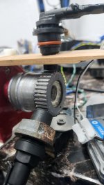
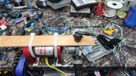
Broke out some lumber and zip ties, solved the new style VSS mounting issues.
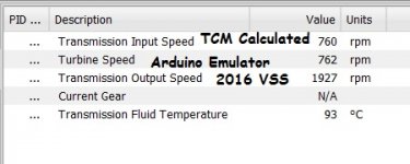
Ran some tests last nigh with a SnapOn scope to look at how these new sensors and the Arduino works with the T87, but our nifty little VR converter doesn't. Looks like it comes down to output amperage limitation of these Max chips. But what I found was interesting is how the TCM guestimates the Input Speed off the Turbine Speed sensor if no CANbus engine RPM value is receive.
For quicker testing I only powered up the T87 on the bench with no ECM connected. Typically the T87 Pid for Input Speed reads the Engine RPM as received by the TCM. But last night I noted that when I connected the Arduino to the Turbine Speed line, the Input value tracked with Turbine. Looks to be some sort of failsafe mode in case the ECM connection is lost. While irrelevant to our discussion, it gives some insight to this TCM OS.
In the screenshot below, I have the Arduino running in place of the Turbine Speed Sensor, and the 2016 Output Shaft Sensor sending live wheel data. Everything looks fine here. So I'm sorting the voltage captures to share for opinions next. For now, some MacGyver pics.