lly ficm emulation

howtonhawky

New member
Dec 6, 2023
5
2
1
catfish69
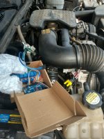
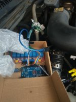
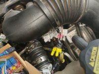
The setup will be for an Arduino UNO board, 8 channel optocoupler and 2 amp 36 v power supply. i have already written most of the code needed to run it. The 8 wires from the ecu wil connect to the 8 channel optocoupler on the no side and the eight wires from the injectors will connect to the cc side of the relay board. we will not use the can bus wires. The crankshaft sensor wire will go to the uno board and the 8 relays inputs will connect to the 8 pins on the uno board. there are 12v hot wires and 2 grnd wires that can be used for the power supply and the output of the 36v will connect to the positive side of the injector wires. This wil allow constant power to the injectors and then the grnd side will be toggled to make the connections during operation. Here is a simplified version of the code to put on the uno board and it has not been tested, #include <EEPROM.h>


// Define relay module pins

const int relayPins[] = {2, 3, 4, 5, 6, 7, 8, 9};


// Crankshaft signal pin with internal pullup resistor

const int crankshaftPin = 10;


// Pulse width and timing settings

const int pulseWidthDelay = 3; // 3 ms

const int timingDelay = 15; // 15 ms


// Variable to store the last used injector index

int lastUsedInjectorIndex = 0;


void setup() {

// Set relay pins as OUTPUT

for (int i = 0; i < 8; i++) {

pinMode(relayPins, OUTPUT);

}


// Set crankshaft pin as INPUT with internal pullup resistor

pinMode(crankshaftPin, INPUT_PULLUP);


// Initialize Serial communication for debugging

Serial.begin(9600);


// Retrieve last used injector index from EEPROM

lastUsedInjectorIndex = EEPROM.read(1);

}


void loop() {

// Read the crankshaft signal

int crankshaftSignal = digitalRead(crankshaftPin);


// Assuming HIGH signal indicates a tooth and LOW indicates a gap

if (crankshaftSignal == HIGH) {

// Determine which injector to engage based on the tooth count

int toothCount = (millis() / 15) % 60;

int injectorIndex = (toothCount / 15) % 8;


// Engage the corresponding injector by activating the relay

digitalWrite(relayPins[injectorIndex], HIGH);


// Update the last used injector index

lastUsedInjectorIndex = injectorIndex;


// Add delay for pulse width

delay(pulseWidthDelay);


// Turn off all injectors

for (int i = 0; i < 8; i++) {

digitalWrite(relayPins, LOW);

}


// Add delay for timing delay

delay(timingDelay);

}

}
 
  • Like
Reactions: turbovan

2004LB7

Well-known member
Dec 15, 2010
6,372
1,733
113
Norcal
Absolutely do not use relays, especially from the Arduino boards, to drive injectors. Good way to burn the injector coil. There is a reason mosfets are used. And you need a way to drop the voltage down to 12 volts quickly after activation of the coil or you'll start overheating the coil and once again risk burning them out

Another point, those relays are only good for about 10 Hz max, so about 1/4 the speed needed to even idle

Been down this road already.
 
Last edited:

howtonhawky

New member
Dec 6, 2023
5
2
1
catfish69
Absolutely do not use relays, especially from the Arduino boards, to drive injectors. Good way to burn the injector coil. There is a reason mosfets are used. And you need a way to drop the voltage down to 12 volts quickly after activation of the coil or you'll start overheating the coil and once again risk burning them out

Another point, those relays are only good for about 10 Hz max, so about 1/4 the speed needed to even idle

Been down this road already.
the system already works for 05 lly. the relays are used on the ground side not the positive side. the power supply at 2 amps 36 v is not too hot to burn the coils out because the actual voltage reaching the injector is less than 2 amps. there are several different types of optocouplers available that operate in the same range as the Arduino.
 

TheBac

Why do I keep doing this?
Staff member
Apr 19, 2008
15,314
1,601
113
Mid Michigan
Seems odd that a brand new member would join here to post something like this without first explaining just who they are and what/why they are adding to our own discussion of the topic. We know the players already working on this.

So, howtonhawky, who are you? Qualifications? We'll need proof your idea is working, not just "take your word for it", as we dont know you.
 

howtonhawky

New member
Dec 6, 2023
5
2
1
catfish69
Seems odd that a brand new member would join here to post something like this without first explaining just who they are and what/why they are adding to our own discussion of the topic. We know the players already working on this.

So, howtonhawky, who are you? Qualifications? We'll need proof your idea is working, not just "take your word for it", as we dont know you.
i am a 05 lly owner that could not pay 2500$ for a fuel module. If you will look at my post i have been here a year or so inquiring about the ficm. studied it based on the wiring on my truck cause there s really no one giving answers on the details. Te first clue i noticed was the 8 grnd wires coming from the ecu to the ficm. The claim was that the wires were for testing but i surmised that that is how they put the trucks in limp mode by regulating the available grnd coming from ecu to ficm. So that means the ficm only gets ground to injectors when the ecu allows it. if a truck is in limp mode you could just put a grnd on those wires and the limp mode would go away. that meant that none of that advancd programming would be necessary in an emulation program and all it would need to do is count the reluctor wheel and engage the grnd side of the injectors at proper time using the grnd from the ecu and the ecu would not really notice. i thought at first that the ecu and ficm would be sharing much information via can bus but then i realized that would have been a slower way for gm to operate the ficm vs just having the ecu give grnd to the ficm when it was necessary.

Actually i have written several versions of programs and now we can control injectors on a v8 using just the crankshaft signal. I am saving those programs for future use. The hard part of running injectors using only crank signal is tricky because of the two different banks of injectors every revolution.

As far a other groups working on this and who i am.. i am just a poor lly owner working alone and that is why none of this has been marketed yet.

Now for the best info i have found during my research is that the actual board in the lly ficm is still in production and being used by Izusu. Also there are several companies out there now that will recreate the module board. If i had money i would do it myself.

So to sum it up this whole lly mess is just tptb have some reason they do not want to fix the mess.

I think it would be interesting to create a program to replace the ecu also and am halfway there.
 
  • Like
Reactions: turbovan

2004LB7

Well-known member
Dec 15, 2010
6,372
1,733
113
Norcal
i am a 05 lly owner that could not pay 2500$ for a fuel module. If you will look at my post i have been here a year or so inquiring about the ficm. studied it based on the wiring on my truck cause there s really no one giving answers on the details. Te first clue i noticed was the 8 grnd wires coming from the ecu to the ficm. The claim was that the wires were for testing but i surmised that that is how they put the trucks in limp mode by regulating the available grnd coming from ecu to ficm. So that means the ficm only gets ground to injectors when the ecu allows it. if a truck is in limp mode you could just put a grnd on those wires and the limp mode would go away. that meant that none of that advancd programming would be necessary in an emulation program and all it would need to do is count the reluctor wheel and engage the grnd side of the injectors at proper time using the grnd from the ecu and the ecu would not really notice. i thought at first that the ecu and ficm would be sharing much information via can bus but then i realized that would have been a slower way for gm to operate the ficm vs just having the ecu give grnd to the ficm when it was necessary.

Actually i have written several versions of programs and now we can control injectors on a v8 using just the crankshaft signal. I am saving those programs for future use. The hard part of running injectors using only crank signal is tricky because of the two different banks of injectors every revolution.

As far a other groups working on this and who i am.. i am just a poor lly owner working alone and that is why none of this has been marketed yet.

Now for the best info i have found during my research is that the actual board in the lly ficm is still in production and being used by Izusu. Also there are several companies out there now that will recreate the module board. If i had money i would do it myself.

So to sum it up this whole lly mess is just tptb have some reason they do not want to fix the mess.

I think it would be interesting to create a program to replace the ecu also and am halfway there.
Videos? Photos? Anything?

Would be interested to see what you got
 

howtonhawky

New member
Dec 6, 2023
5
2
1
catfish69
Also in the code i provided has a limited life span and could be changed to extend it easily. The issue is that the uno eeprom is good for about 1000000 writes and the code writes the eeprom everytime it is used in order to remember the last injector used. It should not be an issue since the code does not do canbus comm that requires writing to the eeprom frequently.

Anyhow if anyone uses this they will need ARDUINO IDE program to write it to an Arduino uno board. There may be an brace out of place im not sure since i have not verified it yet in ide.
 

2004LB7

Well-known member
Dec 15, 2010
6,372
1,733
113
Norcal
I tried something similar and the relays only lasted about a minute before sticking closed. Dangerous for the coils. Inductive loads are hard on the relay contacts and results in arcing and welding closed. Be careful

Also wasn't able to get them to cycle at much over 200 or so RPMs due to the slow reaction time of the relay
 

1FastBrick

Well-known member
Dec 1, 2016
2,192
813
113
Junkyard
Now for the best info i have found during my research is that the actual board in the lly ficm is still in production and being used by Izusu. Also there are several companies out there now that will recreate the module board. If i had money i would do it myself.

So to sum it up this whole lly mess is just tptb have some reason they do not want to fix the mess.

I think it would be interesting to create a program to replace the ecu also and am halfway there.
If the LLY Board is still in production, Then Who is making it? Bosch says its out of production and they do not have service parts or replacements.

If it's currently in use by Izuzu, then why can't we get any through GM???
 
  • Like
Reactions: 2004LB7

1FastBrick

Well-known member
Dec 1, 2016
2,192
813
113
Junkyard
You would've thought Ken or Jason would've found that out a while ago if it were true. They found everything else.
And that's exactly why I asked!!!

So far, Ken is the only person I know of that actually reached out to the original supplier. We know they used simular boards in other european vehicles. Just not this exact board...

The newer ECU's are capable of controlling the injectors with out the use of an FICM so with the rare occasion that any OEM decides to build a system that way going forward, they really aren't needed...
 
  • Like
Reactions: 2004LB7

kidturbo

Piston Tester
Jul 21, 2010
2,320
1,082
113
Somewhere On The Ohio
www.marinemods.us
Also in the code i provided has a limited life span and could be changed to extend it easily. The issue is that the uno eeprom is good for about 1000000 writes and the code writes the eeprom everytime it is used in order to remember the last injector used. It should not be an issue since the code does not do canbus comm that requires writing to the eeprom frequently.

Anyhow if anyone uses this they will need ARDUINO IDE program to write it to an Arduino uno board. There may be an brace out of place im not sure since i have not verified it yet in ide.
Sounds like you've spent a good bit of time working on the control side to get it going. Personally I've always believed the injectors could controlled well enough to fire up directly off of an Arduino board. Think I might of said a Teensy, but none the less, congratulation on demonstrating it can actually be done with one.

It also sounds like you realize the limitations of arduino. Yet if I had a LLY truck with fried FICM and didn't need to drive it much distance, I'd consider giving an aruduino build a try. Because the options are currently somewhere between rewire the truck, or just plant flowers in the bed of it. But literly everything I've done with a Duramax has been stand alone orientated, so hacking up a harness is just second nature. And that that point, I'm making it a LBZ/LMM and done.

However as mentioned above, there is some longevity issues with the off the shelf hardware options to properly fire the injectors. And if there was any remote possibly of a direct replacement board out there, feel pretty certain I would have ran across it by now. Have found several pieces that look and smell like it, but upon closer inspection. not capable of doing 8 injectors. Could we stack a pair 4cyl Isuzu control units and make it run a truck, I'm down helping wire that up tomorrow. :)
 

kidturbo

Piston Tester
Jul 21, 2010
2,320
1,082
113
Somewhere On The Ohio
www.marinemods.us
And that's exactly why I asked!!!

So far, Ken is the only person I know of that actually reached out to the original supplier. We know they used simular boards in other european vehicles. Just not this exact board...

The newer ECU's are capable of controlling the injectors with out the use of an FICM so with the rare occasion that any OEM decides to build a system that way going forward, they really aren't needed...
I also now have the raw bin files pulled from both LB7 and LLY FICM processors, which yielded 512KB of total nothingness.. Looks to be straight machine language only, an no common structure between the two. Making nothing stored in there of any use. But a single line of data on one of those custom chips, lead me to a possible hardware designer. And yet another dead end. Sticking a fork in the idea of swapping OS between the two units.

What I feel the Ardunio code and hardware above could easily be modified to do, is make a LLY to LB7 hardware adapter. By simply removing the need to store any crank position data, one could easly write a script that just flops the input Control signals, and corrects the crank signal voltage fed to the FICM. 9 wires spliced, and your up and running with a LB7 FICM inside a LLY case.. CANbus data is darn close between em. 50/50 on if it it sets a check engine light, the LLY contains "1" extra bytes missing from the LB7. But if your LLY is currently parked with smoked FICM, this option will get ya rolling.

That's how I see an arduino board getting my butt reliably to work and back every day, for a couple hours labor, and $100 in off the shelf hardware.. If ya can score a LB7 FICM for cheap.
 

JoshH

Daggum farm truck
Staff member
Vendor/Sponsor
Feb 14, 2007
13,597
629
113
Texas!!!
i am a 05 lly owner that could not pay 2500$ for a fuel module. If you will look at my post i have been here a year or so inquiring about the ficm.
What's the name you've been using for the past year then? It shows your join date as Dec 6 of this year. That's the reason we're all so skeptical of your info. A few members here have been working very diligently on a solution, and you come in with info that doesn't match anything anyone else has discovered. Another thing to consider is someone else posted there were some guys in a facebook group claiming to be working on the same thing, but they didn't have any real info to share. No offense to you, but since we don't know you, it seemed a lot like maybe you were one of those guys fishing for info and acting like you had information to exchange.
 
  • Like
Reactions: 2004LB7