Episode 26:
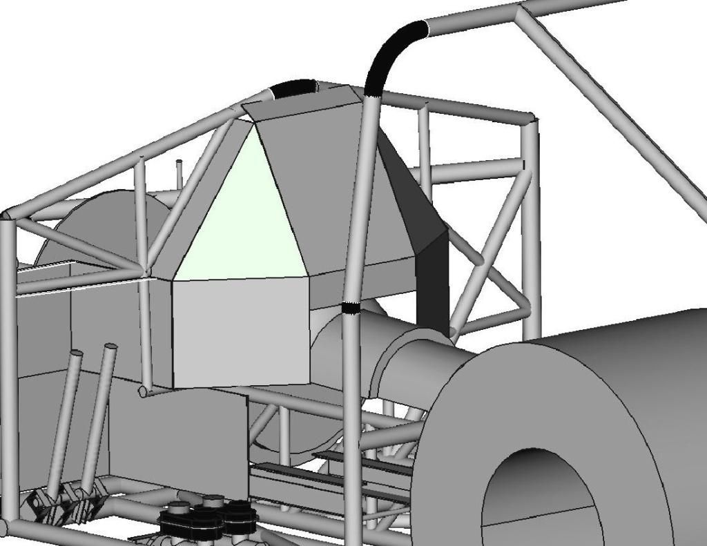
I was nearing the time to order more 1" tubing to form the structure of the firewall, so I got back on the CAD system to figure out how the plates of the firewall would be positioned, so I could order that material at the same time and save on shipping.
With the amount of engine setback (necessary for good weight distribution with the heavy diesel engine), I would have the plane of the flexplate/flywheel at my shins, and my feet would be next to the rear portion of the oil pan (where connecting rods occasionally peek out like a metal groundhog on steroids). To keep from gaining the nickname 'Stumpy" I want the vertical portions of the "footbox" section to be 0.125" 4130 plate. The horizontal and angled portions will be 0.080" thick 4130, still much more protection than the required 0.024" mild steel.
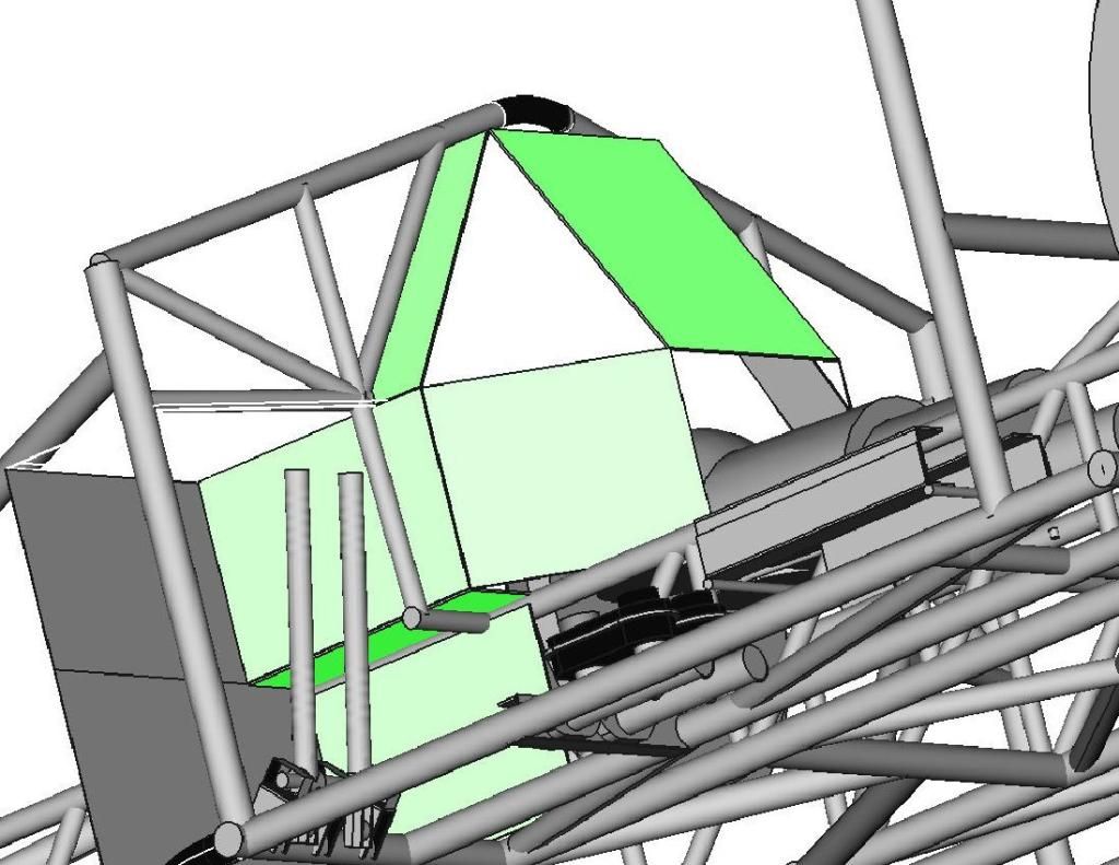
The top area of that center section will be protecting me from shrapnel in the event of a high pressure turbo failure, so that part is important too!
While I have been happy with the freeware 3D CAD program (FreeCAD 13), it does have a few shortcomings and bugs in it. It is very easy to create rectangular and cylindrical shaped solids, but to get the triangular shape to fill in the opening in the above picture, I needed to cut two sections from a rectangle. Once I tried to rotate the part in space it would screw up the cuts. I finally figured out that it could rotate the part if it was part of an assembly or "union" but not by itself, so I created a little speck of dust (0.01 mm cube) that I "assembled" as a union with my desired triangle, then it allowed me to rotate it into position. I had to repeat the "union" process to rotate it about another axis, but it all worked out.
Now that I had all of the plate sections worked out, I needed to figure out how to best fit those shapes into a single plate of material, so I could minimize the material and shipping costs. I switched over to the 2D CAD program and played around with the shapes like a giant puzzle, moving them around until I had the least amount of wasted material.
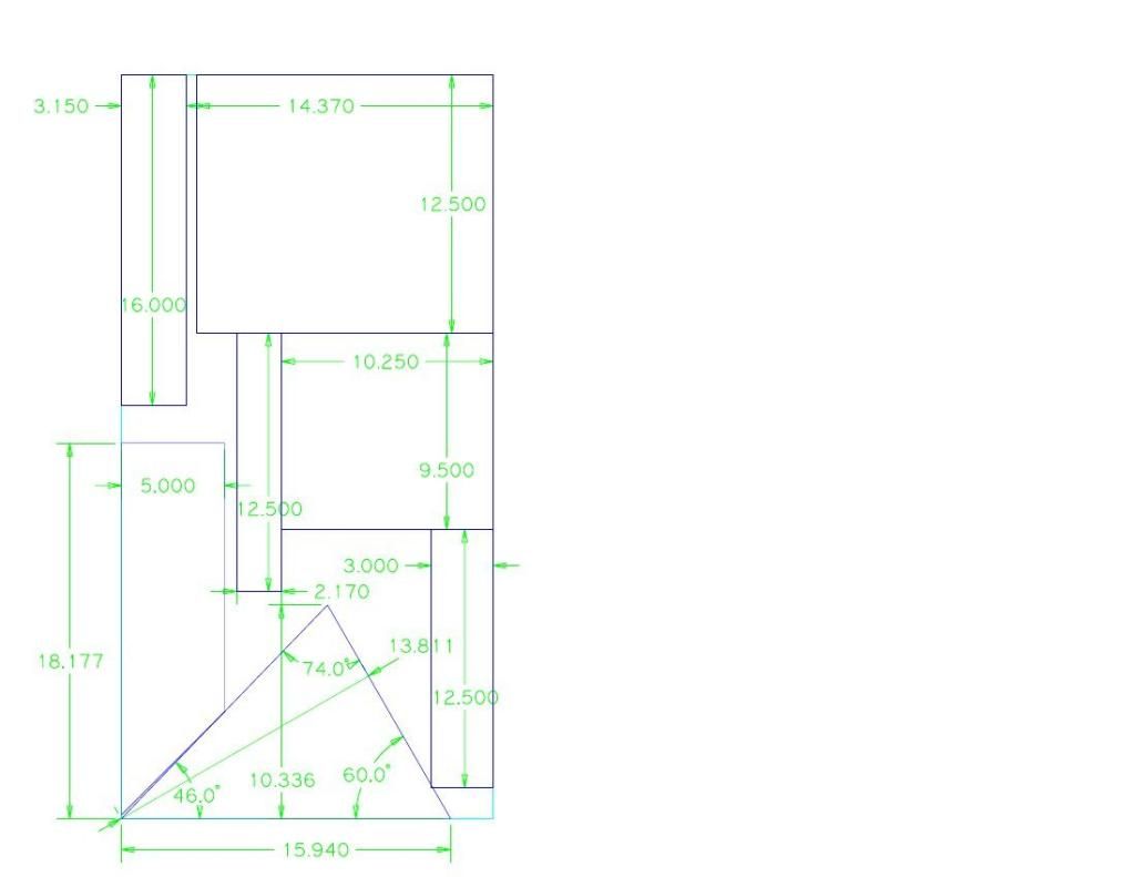
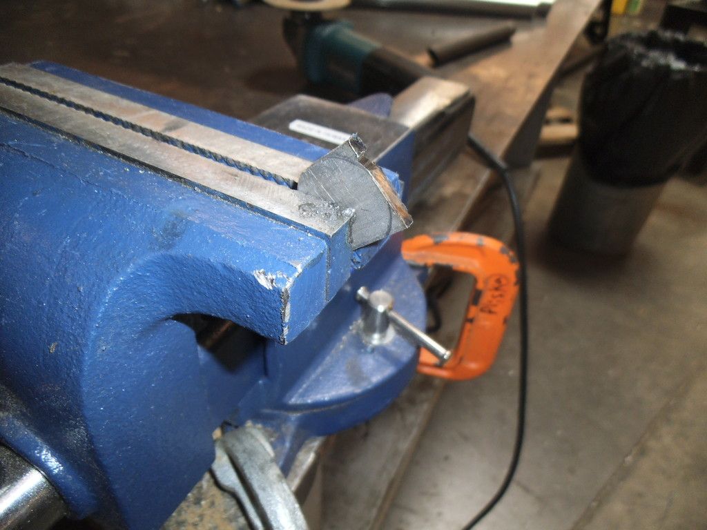
I plan to use my plasma cutter for the necessary "jagged" cuts, but then use a big metal shear to make the straight cuts.
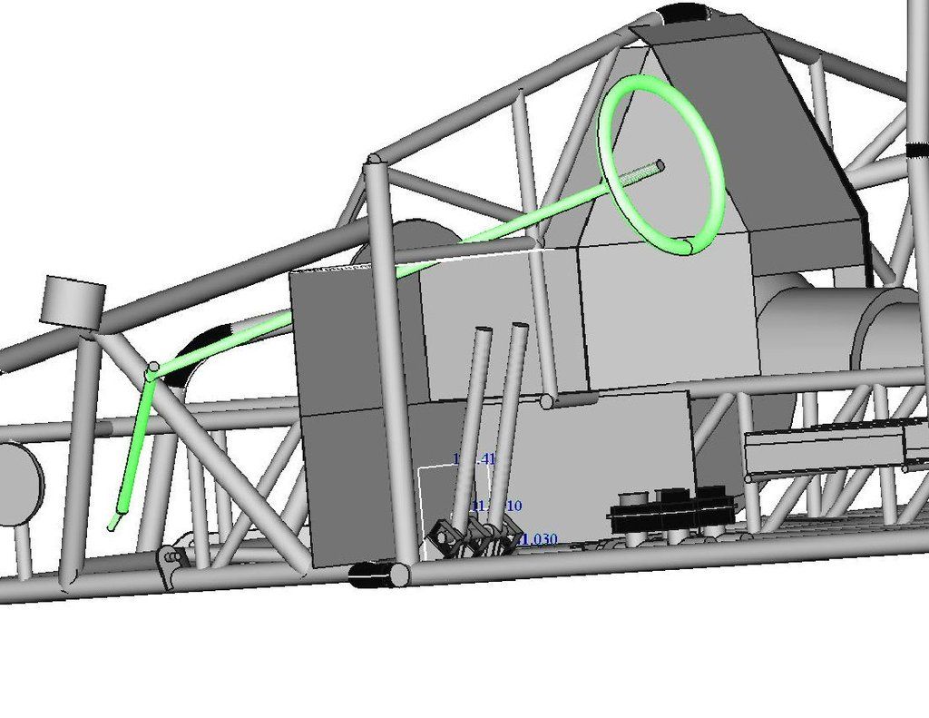
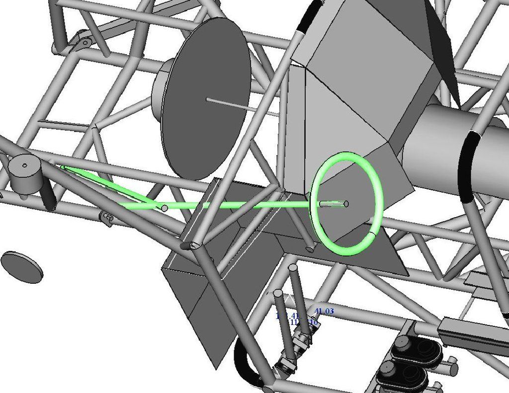
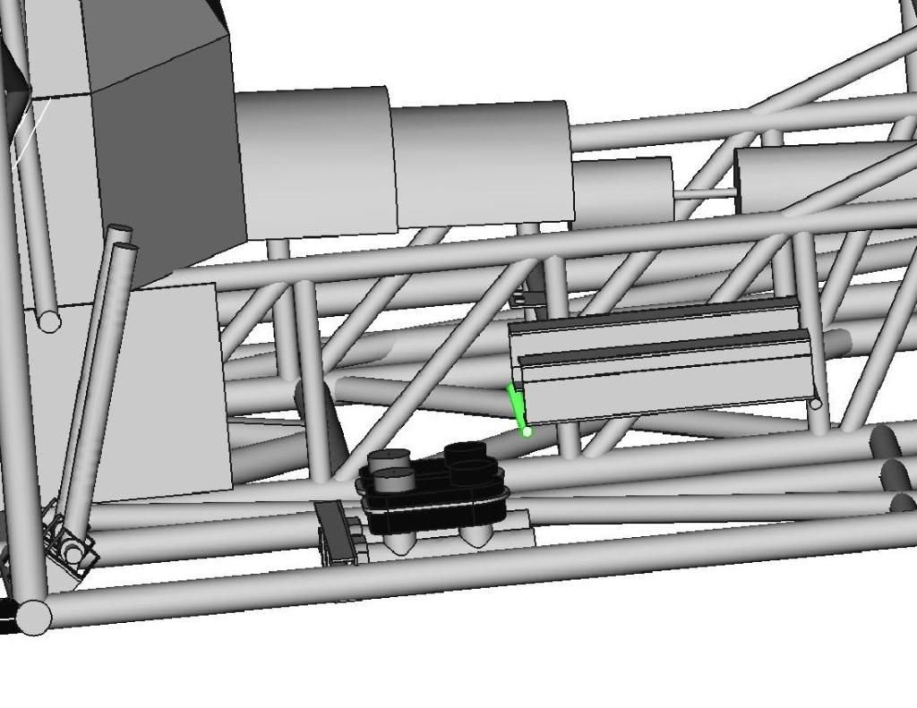
While I was doing all this CAD work I decided to go back to the seat mount design I was working on before. I had previously designed mounts for the master cylinders and brake pedals, and had placed the master cylinders as far back as possible, figuring I would want more of an open floor in front of the seat.
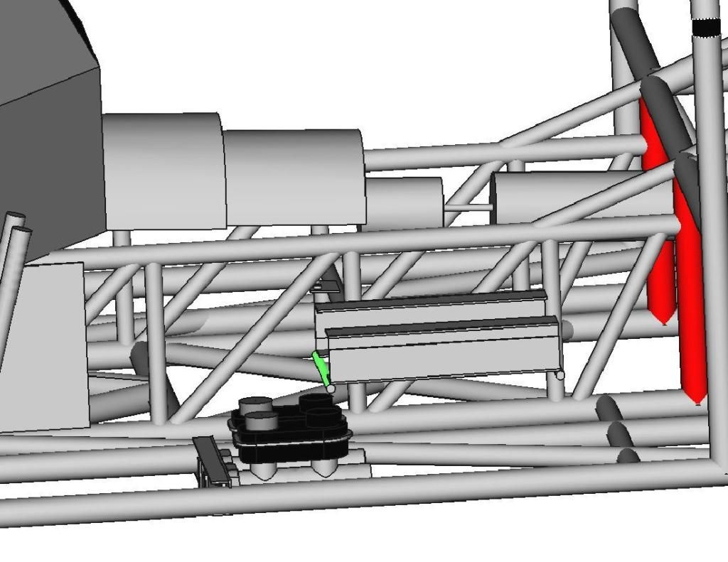
Unfortunately this placed the seat mounts directly over the master cylinder rear caps, and compromised the geometry of the mounts. It was a lot easier to move these in CAD than it would have been after welding! I just moved the whole assembly forward 50mm and gained the clearance I needed.
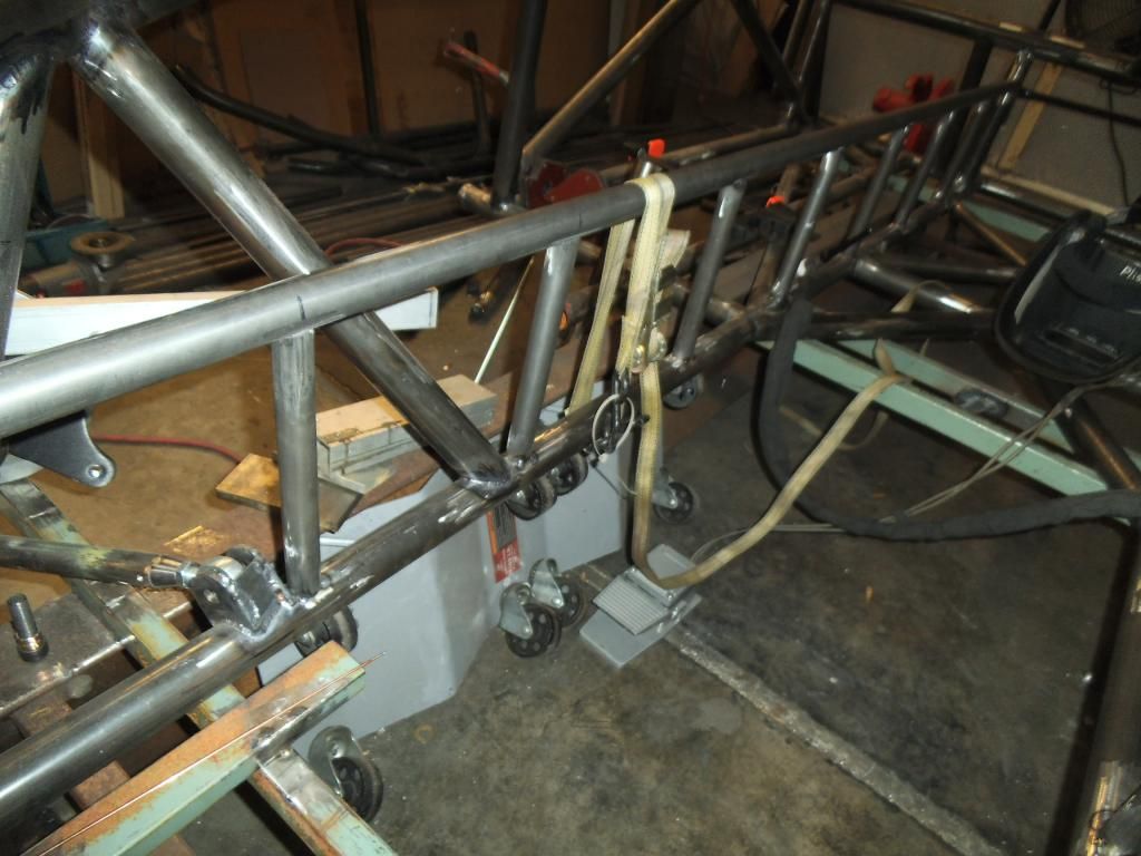
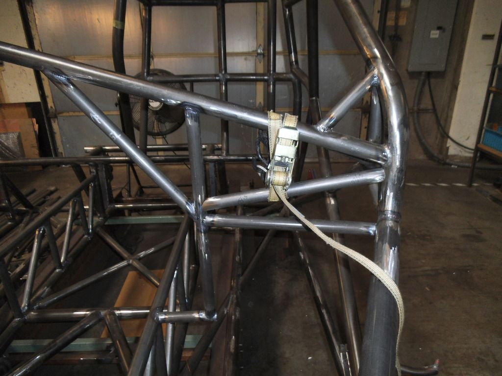
Continuing on the double rails, once I got to the intermediate vertical tubes I used a ratchet strap and clamp to squeeze the top tube down, hopefully holding everything in alignment.
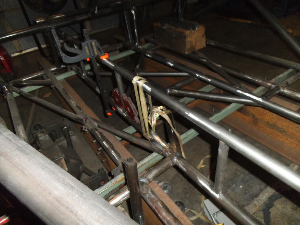
I tried experimenting with that approach versus a "freehand" approach using the digital angle finder like I did the end ones, it was almost a toss up between the time spent setting up the clamps and tube versus taking a little more care with the angle finder and quickly moving from one side to the other on my tack welds (so the weld draw on each side could pull against each other).
I ran all of the truly vertical double frame rail supports (5 of them) on one side, then did the mirror image on the other side.
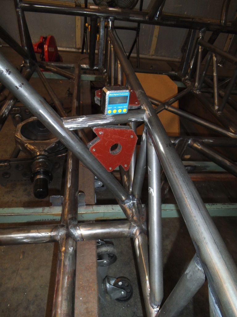
The "vertical" supports that coincide with the engine mount front plate and the mid plate will both be slanted back 2.9° from vertical, to match the slope of the engine/trans (so I have full engagement with these tubes when I weld brackets on at that 2.9° angle). Since the digital protractor was referencing horizontal instead of vertical, the 2.9° angle shows up as 87.1°. And you thought you would never use geometry again after school...
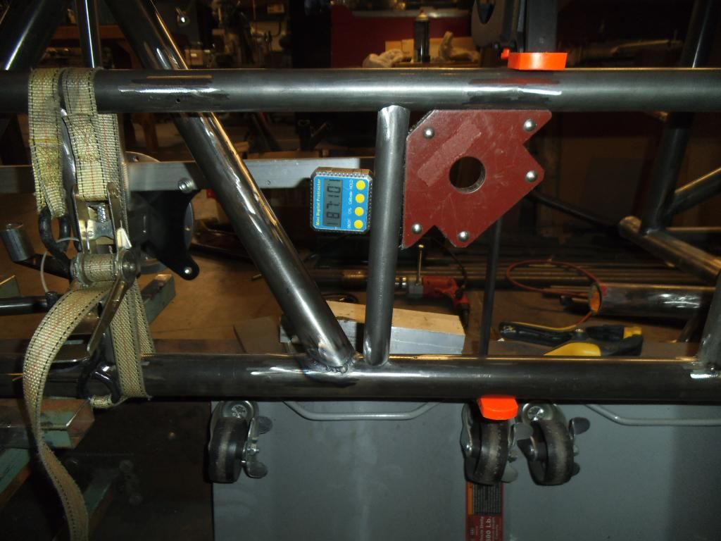
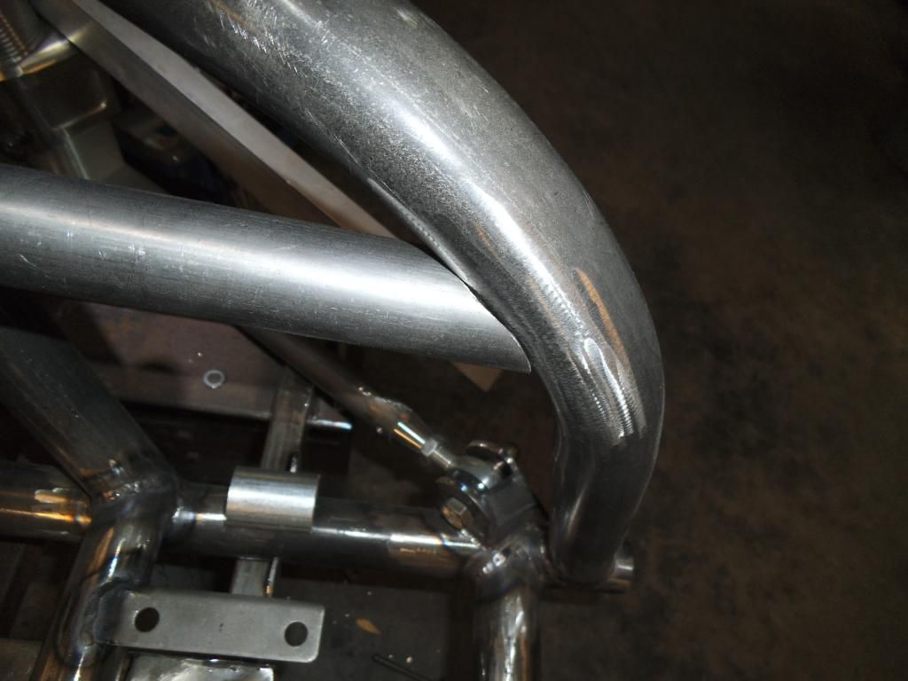
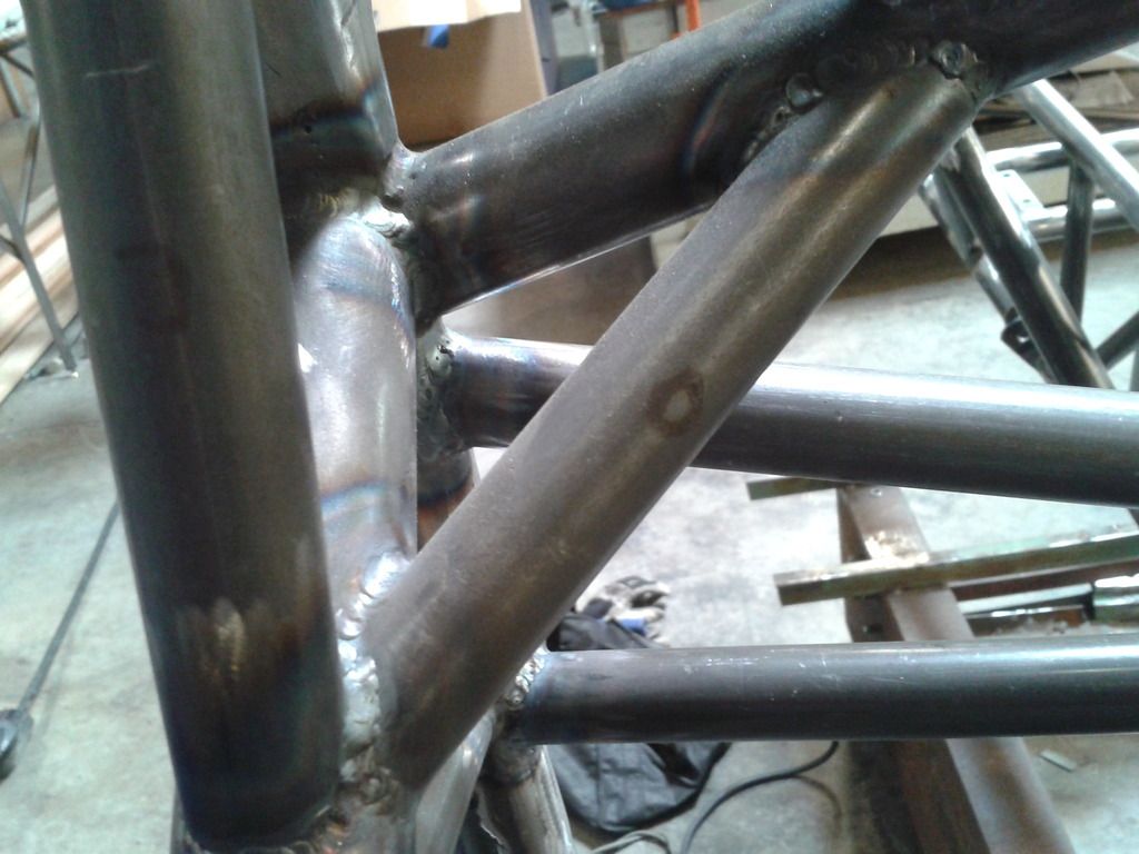
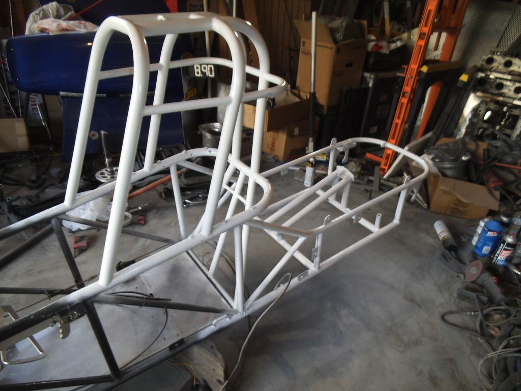
All of those vertical braces were much easier to insert into place with the top rails not welded in yet (as they would require separation of the bottom and top rails to "pop" into place). In this photo you can see the 2.9° tubes, where the front plate of the engine mount will eventually go.
On all of these tubes I was tacking in four opposite spots, to keep the tubes securely positioned. Due to weld draw, I will wait until the whole assembly is tacked together before finish welding it.
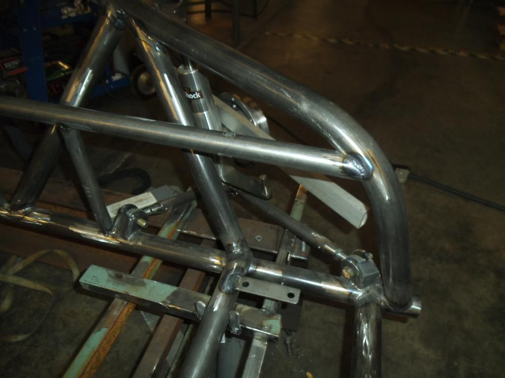
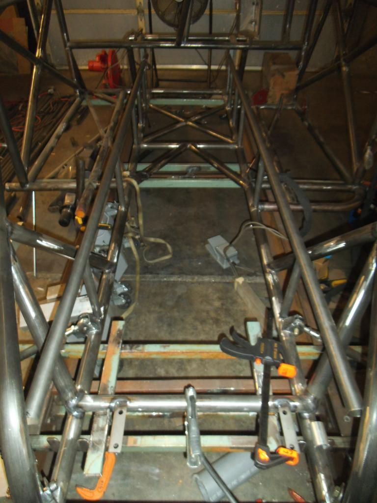
Before I got too far I decided to verify that I had the planned clearance between the seat and the double frame rails. While it is nice to lay this stuff out in CAD, I always feel better when I can see the clearance in the real world!
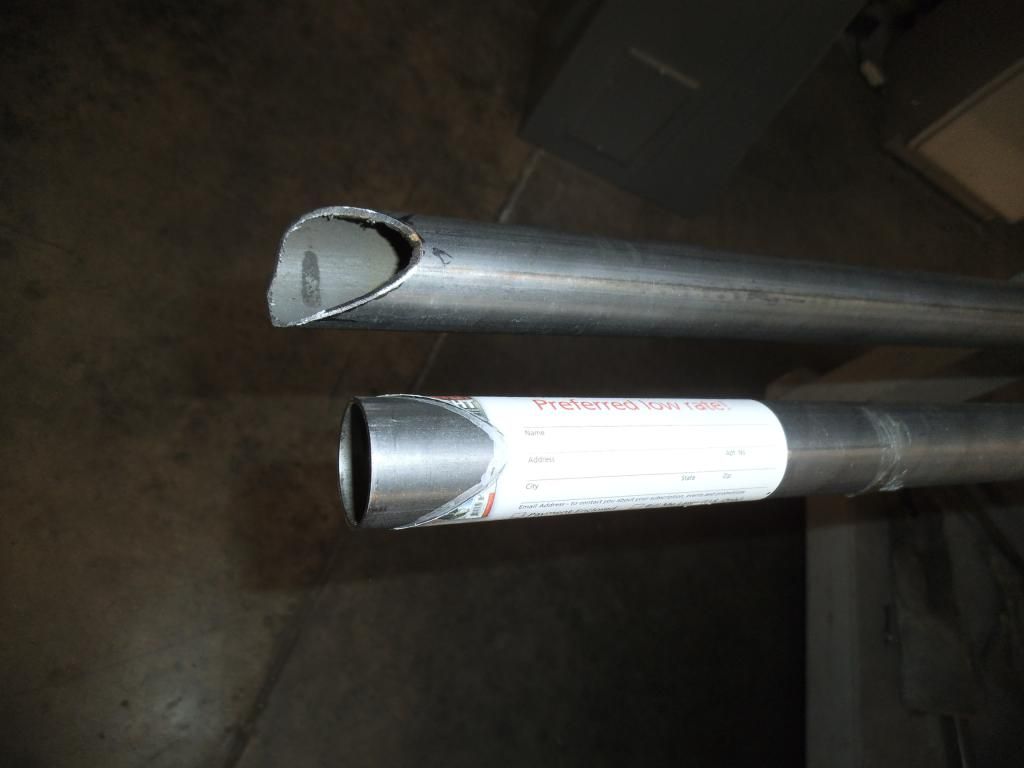
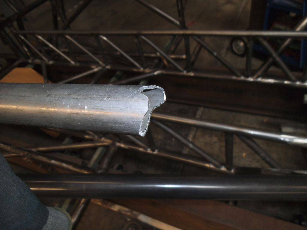
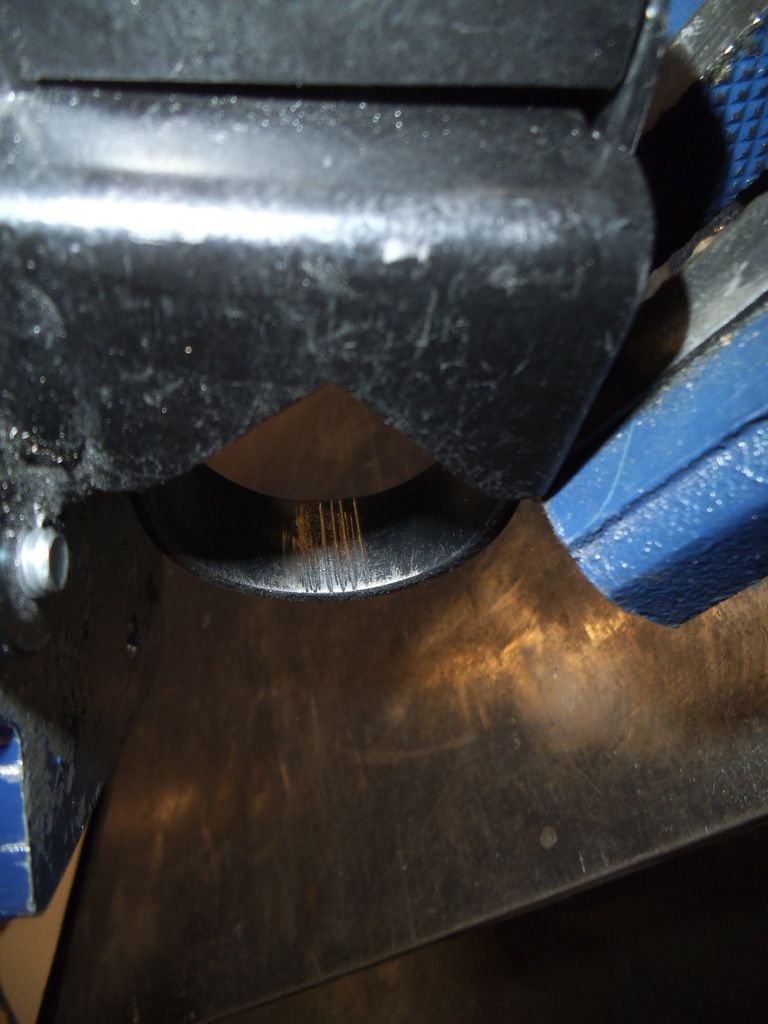
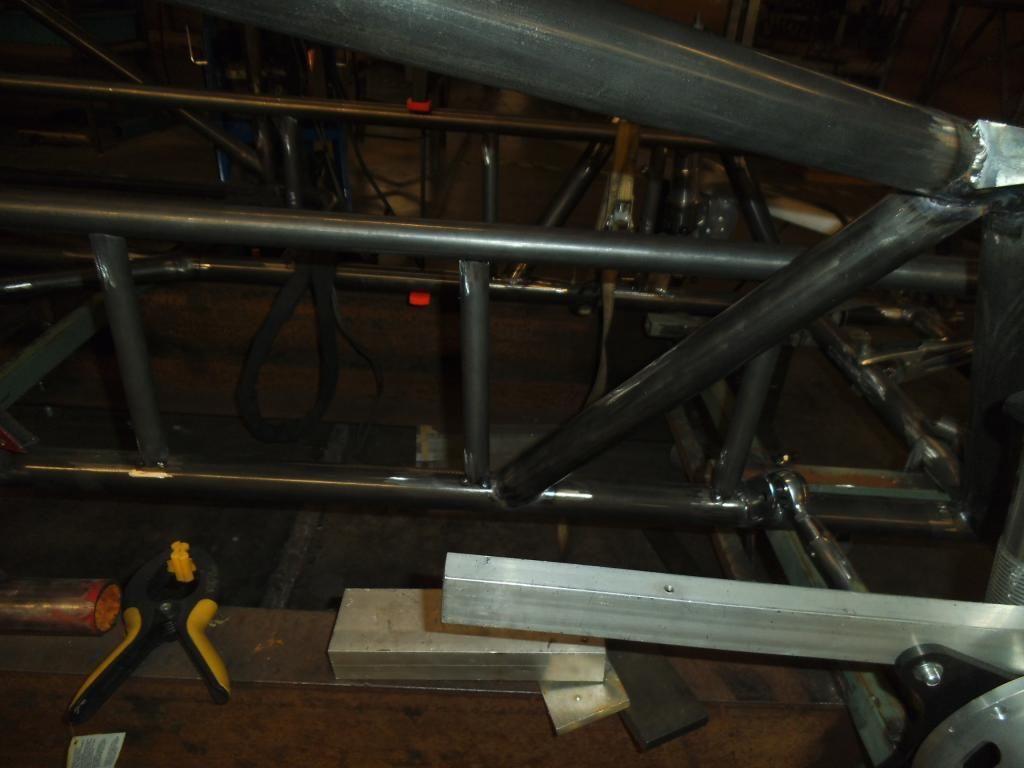
The front edge of the top double frame rails shows the weird compound angle I will have to notch next. Not looking forward to that one!
Of course when things seem to be going well, something weird has to go wrong! This was a weird freak occurrence but something you have to be careful about when working around hot items and a roll cage! I had just finished a weld in an awkward position, went to climb out of the cage and smacked my head & welding hood on the top of the cage, which swung the hood down over my face just as the still-red-hot filler rod caught one of the double frame rail tubes, flipping its hot end right into my chin and under the hood (making it VERY hard to get out). I could hear the flesh searing as I tried to grab the damn thing, and it scooted along a nice straight line as I tried to extricate it!
Next up is the last pair of frame rail uprights, then the aforementioned nightmare notching of the top tubes, tacking them in place, then the 45° diagonals for the double rails. After that it will be on to the tubing forming the firewall, before I move the whole chassis forward on the jig to continue on the rear tubes.
I was nearing the time to order more 1" tubing to form the structure of the firewall, so I got back on the CAD system to figure out how the plates of the firewall would be positioned, so I could order that material at the same time and save on shipping.
With the amount of engine setback (necessary for good weight distribution with the heavy diesel engine), I would have the plane of the flexplate/flywheel at my shins, and my feet would be next to the rear portion of the oil pan (where connecting rods occasionally peek out like a metal groundhog on steroids). To keep from gaining the nickname 'Stumpy" I want the vertical portions of the "footbox" section to be 0.125" 4130 plate. The horizontal and angled portions will be 0.080" thick 4130, still much more protection than the required 0.024" mild steel.
The top area of that center section will be protecting me from shrapnel in the event of a high pressure turbo failure, so that part is important too!
While I have been happy with the freeware 3D CAD program (FreeCAD 13), it does have a few shortcomings and bugs in it. It is very easy to create rectangular and cylindrical shaped solids, but to get the triangular shape to fill in the opening in the above picture, I needed to cut two sections from a rectangle. Once I tried to rotate the part in space it would screw up the cuts. I finally figured out that it could rotate the part if it was part of an assembly or "union" but not by itself, so I created a little speck of dust (0.01 mm cube) that I "assembled" as a union with my desired triangle, then it allowed me to rotate it into position. I had to repeat the "union" process to rotate it about another axis, but it all worked out.
Now that I had all of the plate sections worked out, I needed to figure out how to best fit those shapes into a single plate of material, so I could minimize the material and shipping costs. I switched over to the 2D CAD program and played around with the shapes like a giant puzzle, moving them around until I had the least amount of wasted material.
I plan to use my plasma cutter for the necessary "jagged" cuts, but then use a big metal shear to make the straight cuts.
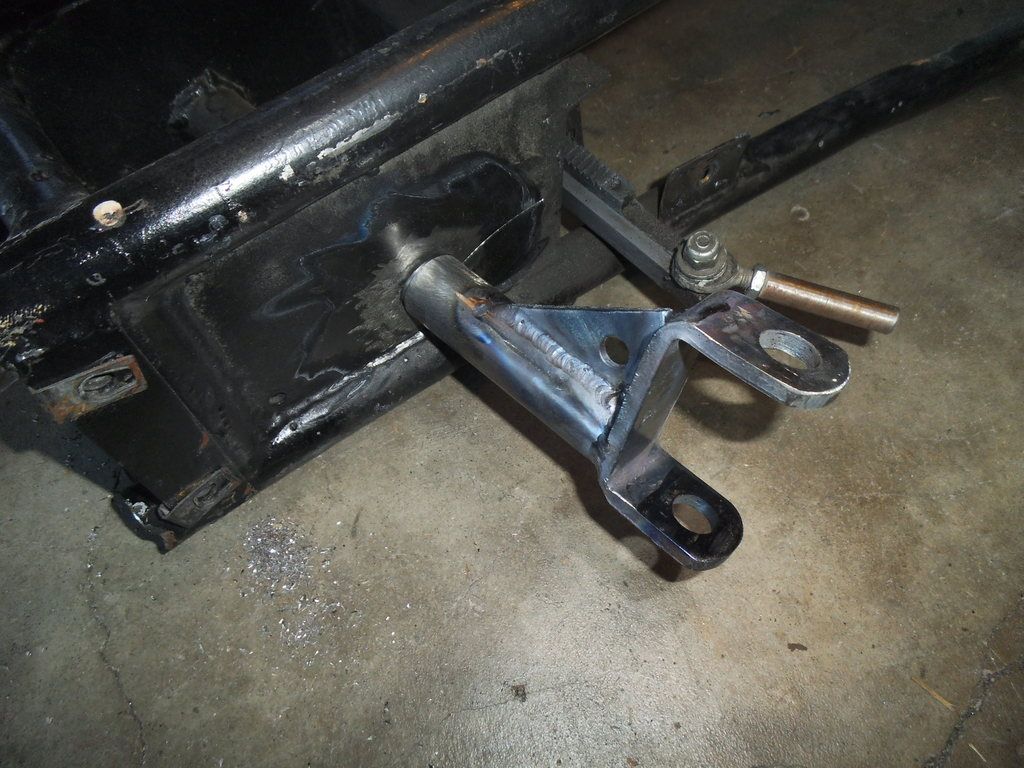
While I was doing all this CAD work I decided to go back to the seat mount design I was working on before. I had previously designed mounts for the master cylinders and brake pedals, and had placed the master cylinders as far back as possible, figuring I would want more of an open floor in front of the seat.
Unfortunately this placed the seat mounts directly over the master cylinder rear caps, and compromised the geometry of the mounts. It was a lot easier to move these in CAD than it would have been after welding! I just moved the whole assembly forward 50mm and gained the clearance I needed.
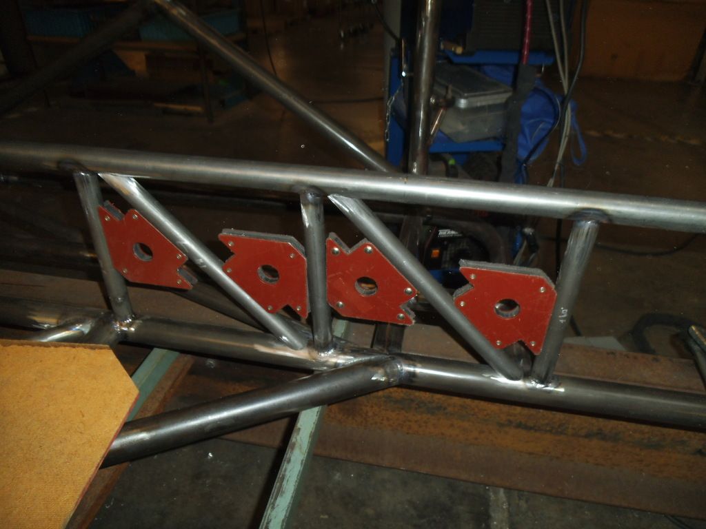
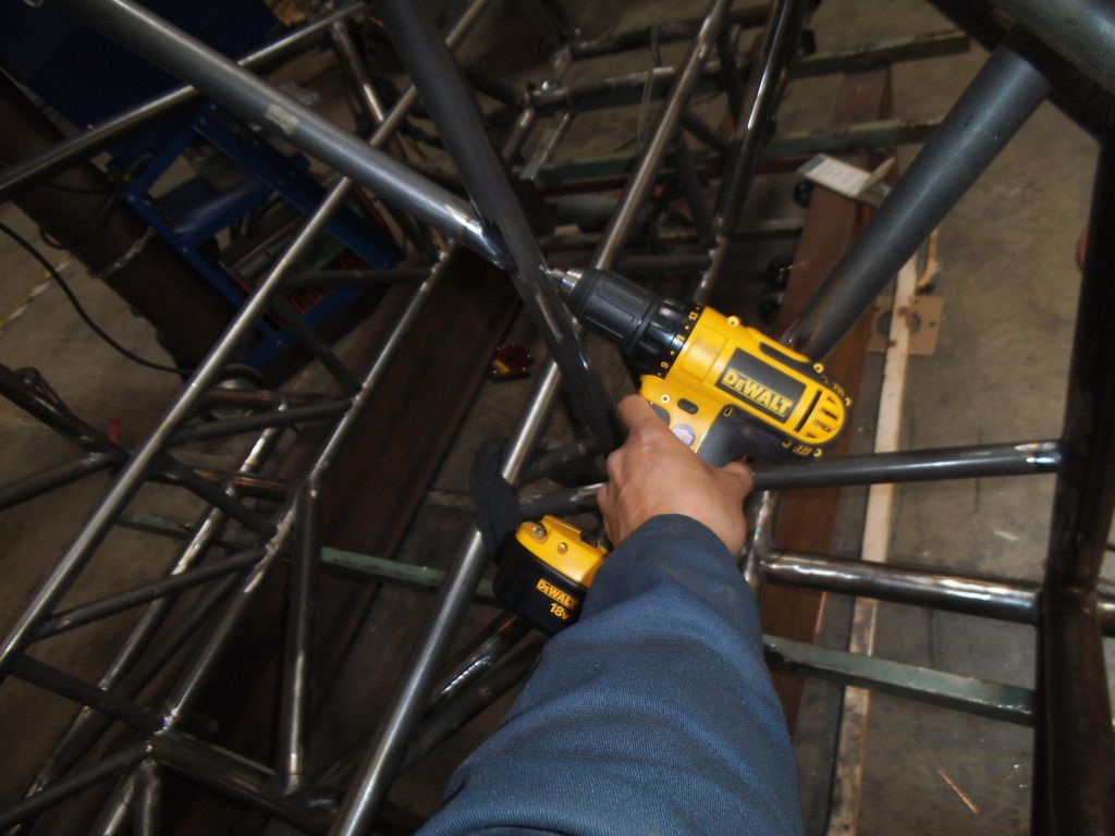
Continuing on the double rails, once I got to the intermediate vertical tubes I used a ratchet strap and clamp to squeeze the top tube down, hopefully holding everything in alignment.
I tried experimenting with that approach versus a "freehand" approach using the digital angle finder like I did the end ones, it was almost a toss up between the time spent setting up the clamps and tube versus taking a little more care with the angle finder and quickly moving from one side to the other on my tack welds (so the weld draw on each side could pull against each other).
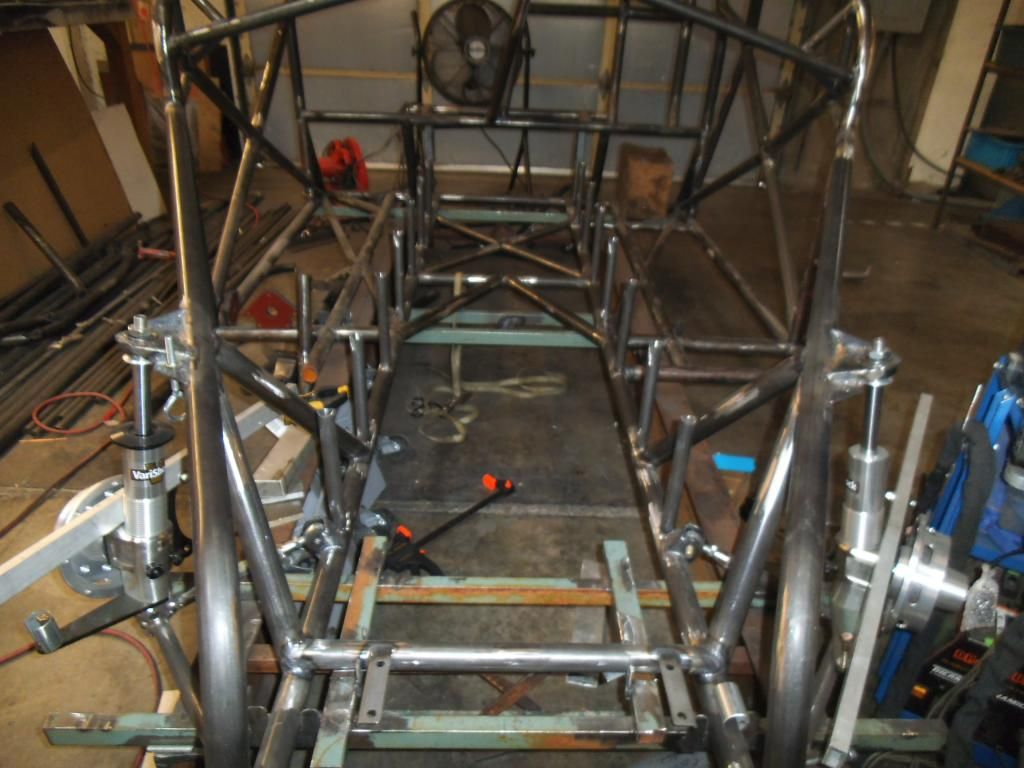
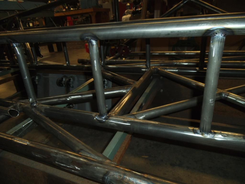
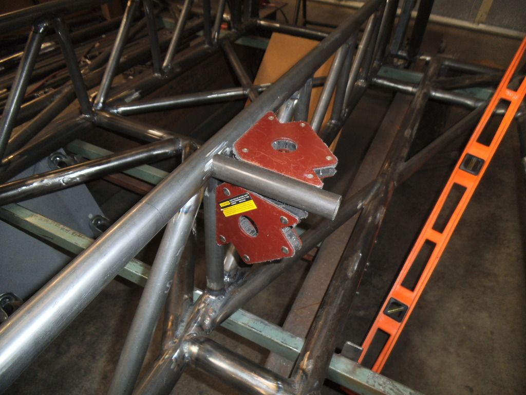
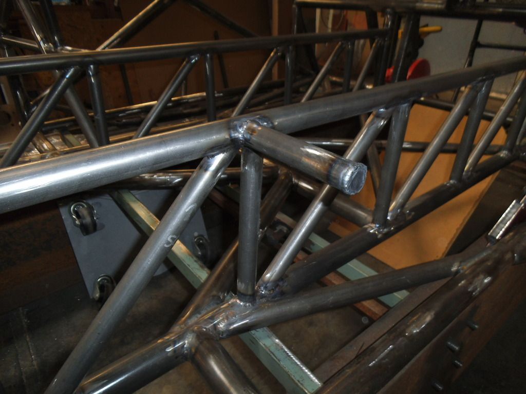
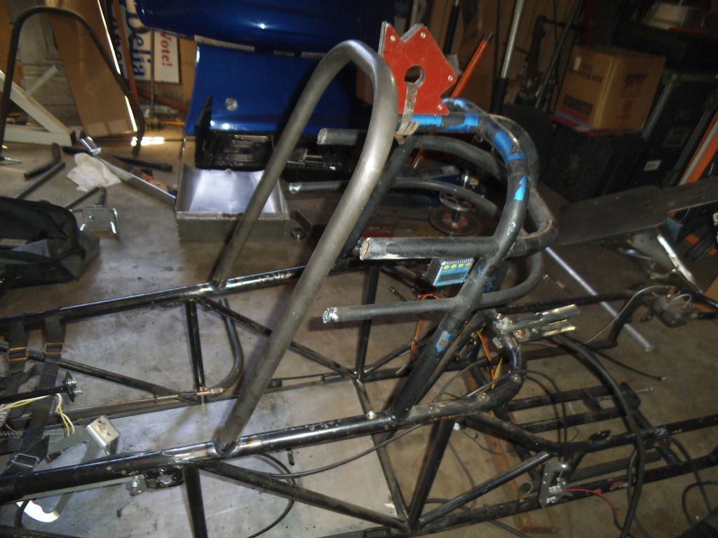
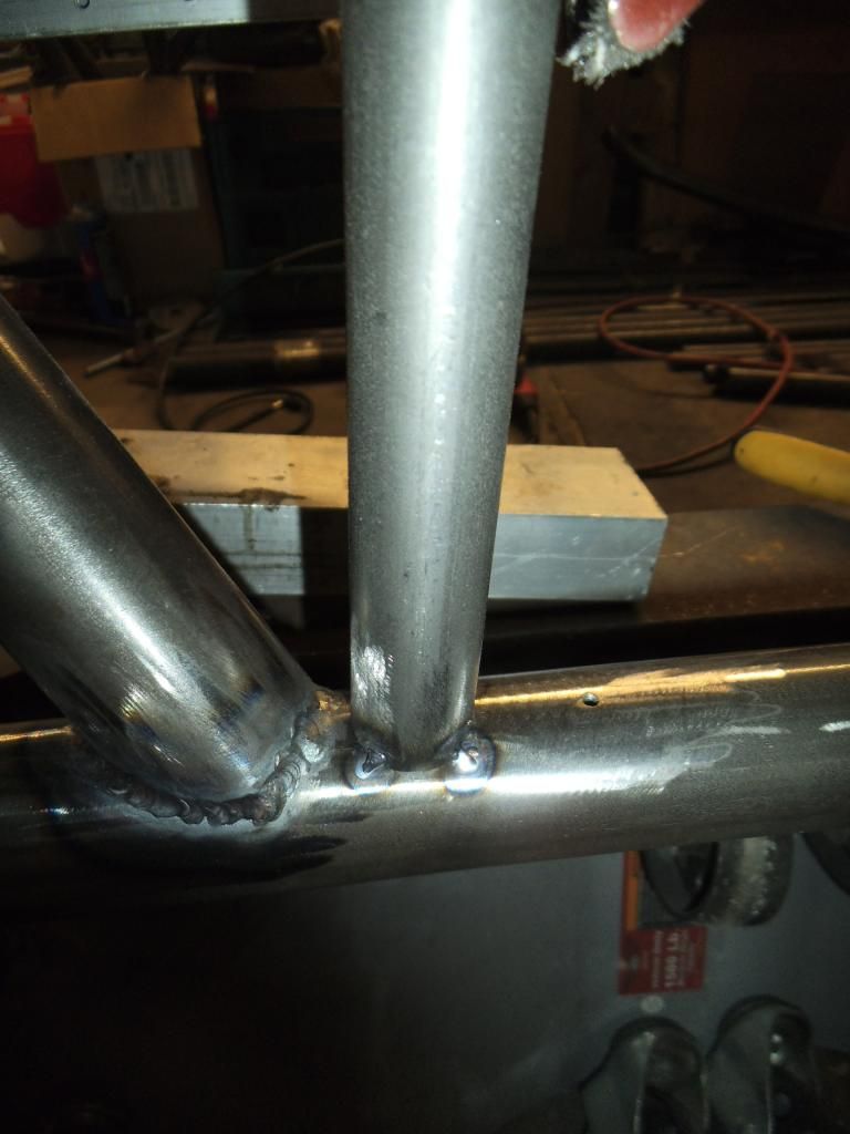
I ran all of the truly vertical double frame rail supports (5 of them) on one side, then did the mirror image on the other side.
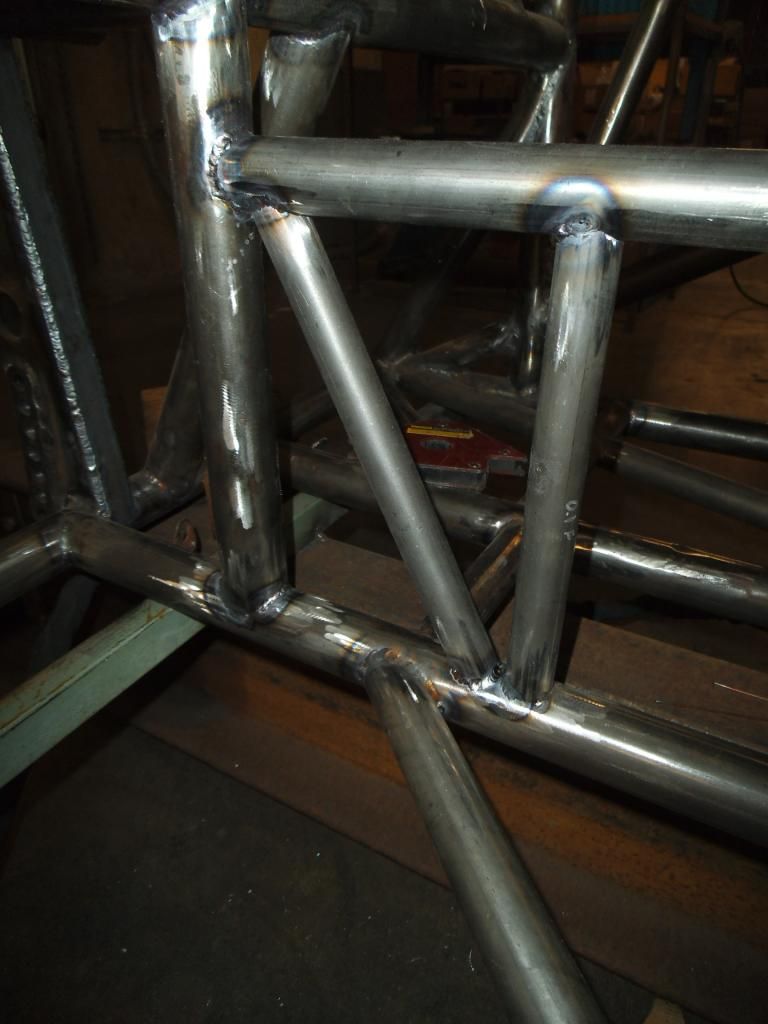
The "vertical" supports that coincide with the engine mount front plate and the mid plate will both be slanted back 2.9° from vertical, to match the slope of the engine/trans (so I have full engagement with these tubes when I weld brackets on at that 2.9° angle). Since the digital protractor was referencing horizontal instead of vertical, the 2.9° angle shows up as 87.1°. And you thought you would never use geometry again after school...
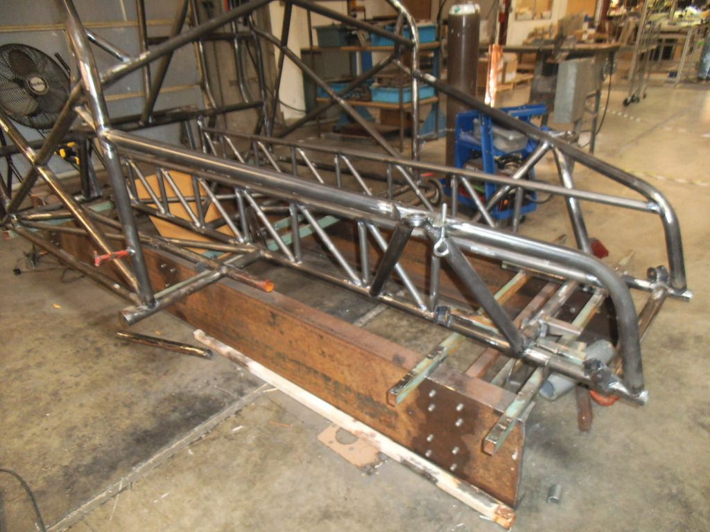
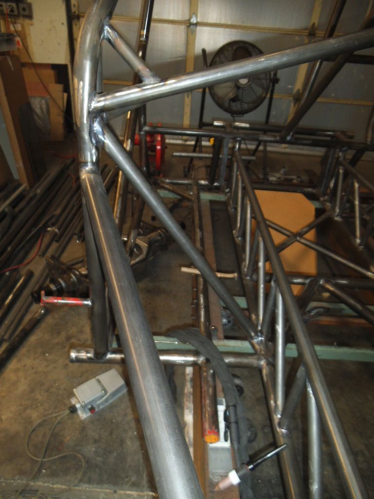
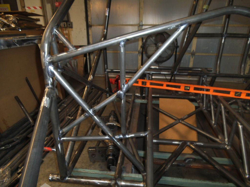
All of those vertical braces were much easier to insert into place with the top rails not welded in yet (as they would require separation of the bottom and top rails to "pop" into place). In this photo you can see the 2.9° tubes, where the front plate of the engine mount will eventually go.
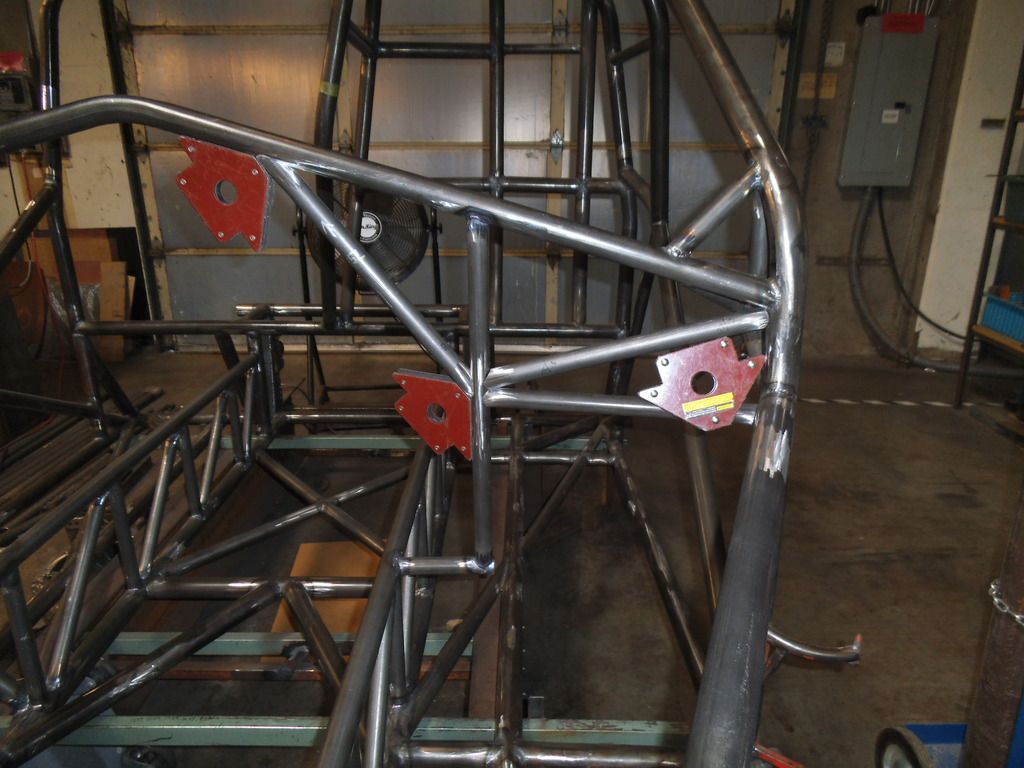
On all of these tubes I was tacking in four opposite spots, to keep the tubes securely positioned. Due to weld draw, I will wait until the whole assembly is tacked together before finish welding it.
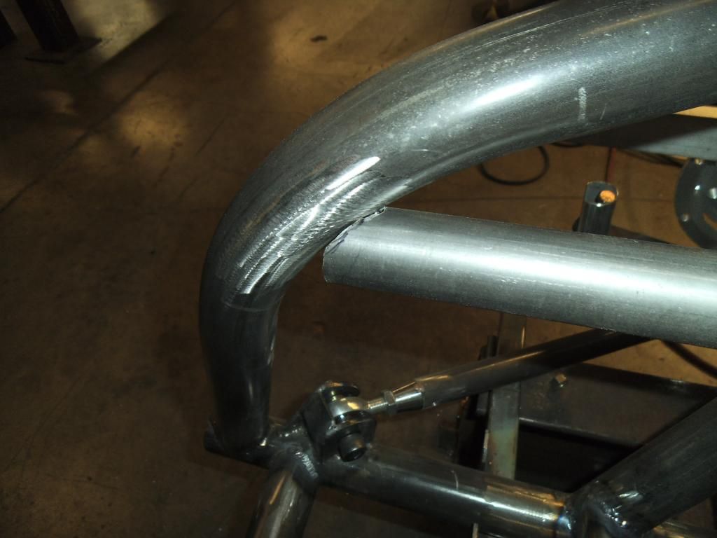
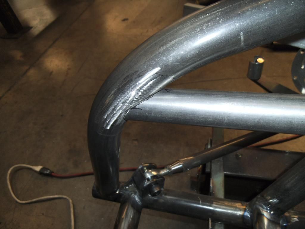
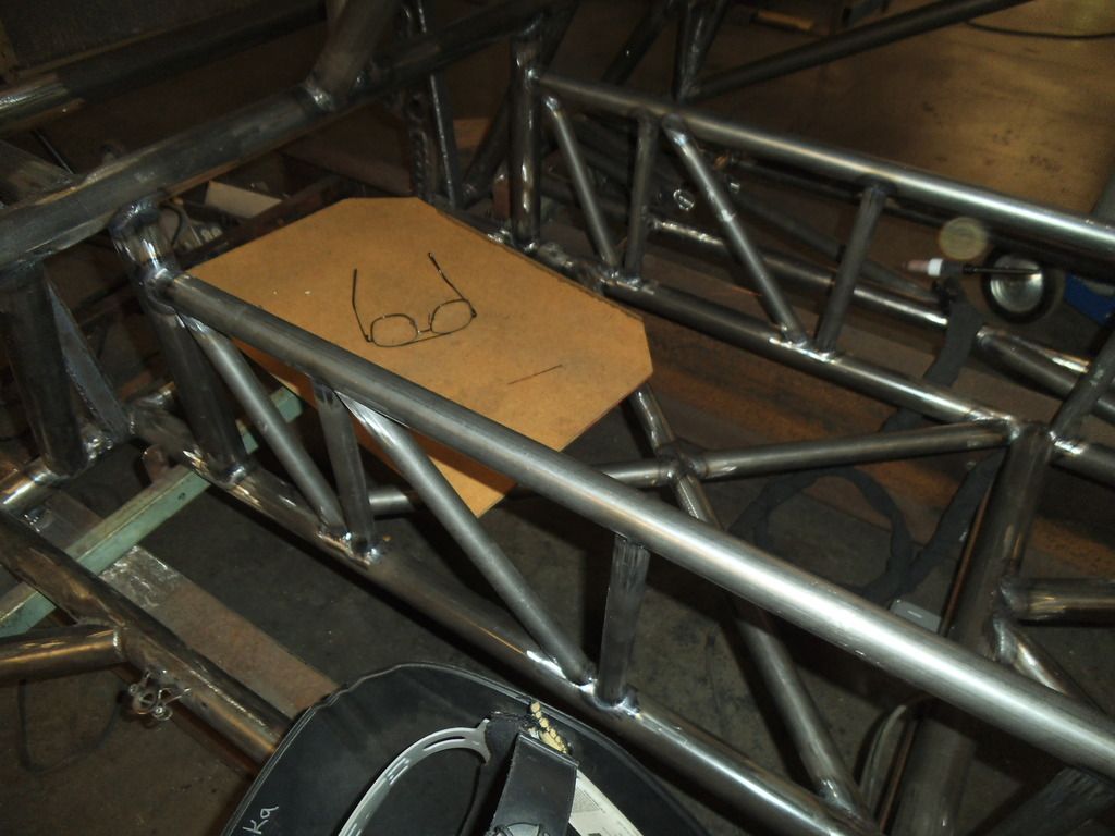
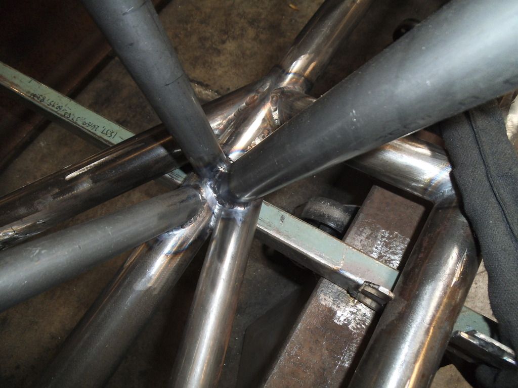
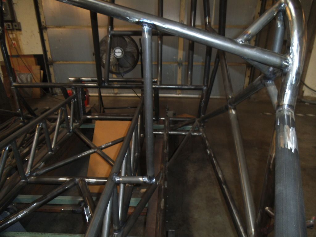
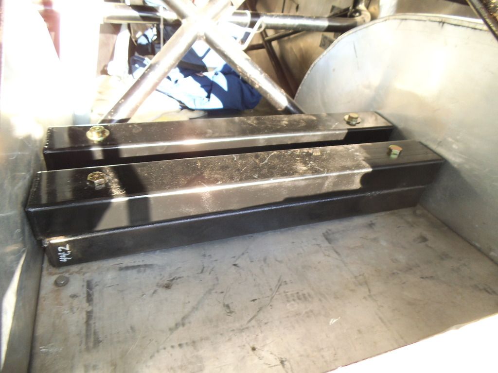
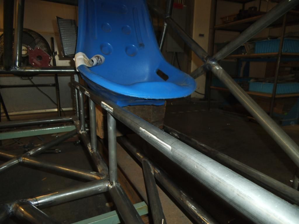
Before I got too far I decided to verify that I had the planned clearance between the seat and the double frame rails. While it is nice to lay this stuff out in CAD, I always feel better when I can see the clearance in the real world!
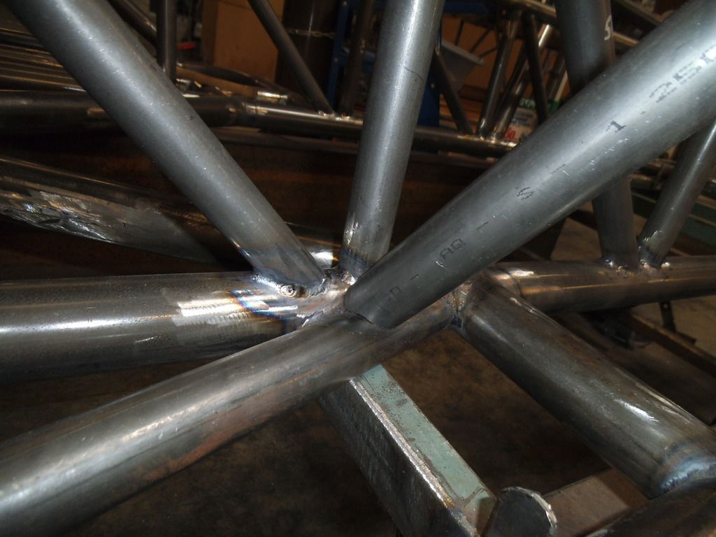
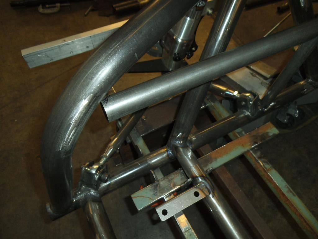
The front edge of the top double frame rails shows the weird compound angle I will have to notch next. Not looking forward to that one!
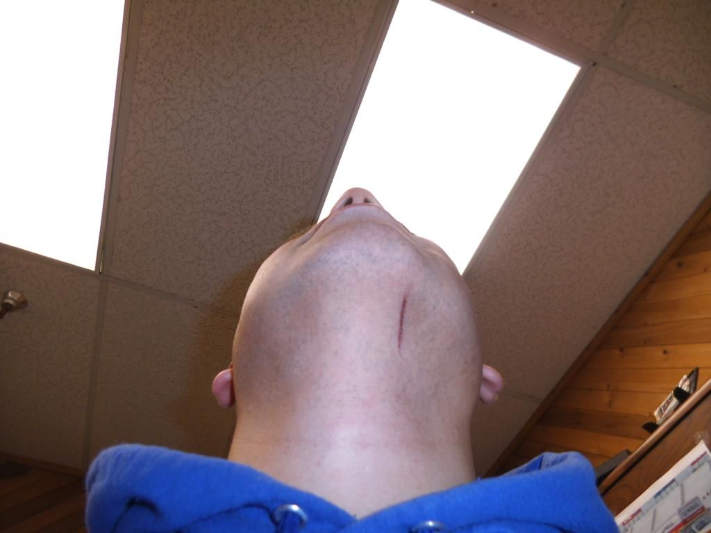
Of course when things seem to be going well, something weird has to go wrong! This was a weird freak occurrence but something you have to be careful about when working around hot items and a roll cage! I had just finished a weld in an awkward position, went to climb out of the cage and smacked my head & welding hood on the top of the cage, which swung the hood down over my face just as the still-red-hot filler rod caught one of the double frame rail tubes, flipping its hot end right into my chin and under the hood (making it VERY hard to get out). I could hear the flesh searing as I tried to grab the damn thing, and it scooted along a nice straight line as I tried to extricate it!
Next up is the last pair of frame rail uprights, then the aforementioned nightmare notching of the top tubes, tacking them in place, then the 45° diagonals for the double rails. After that it will be on to the tubing forming the firewall, before I move the whole chassis forward on the jig to continue on the rear tubes.