Episode 21
I swear there is always something that keeps me from spending time on this build. In this case I lost a few days to clearing up a case of ID theft! I went to file my taxes and found out that someone had already filed a fraudulent return using my information. It turns out that a large percentage of people who volunteer for Catholic schools in our part of the country had this happen, apparently by someone in the company they used for the legally required background checks. Too bad they couldn't have paid the tax bill I actually had due!
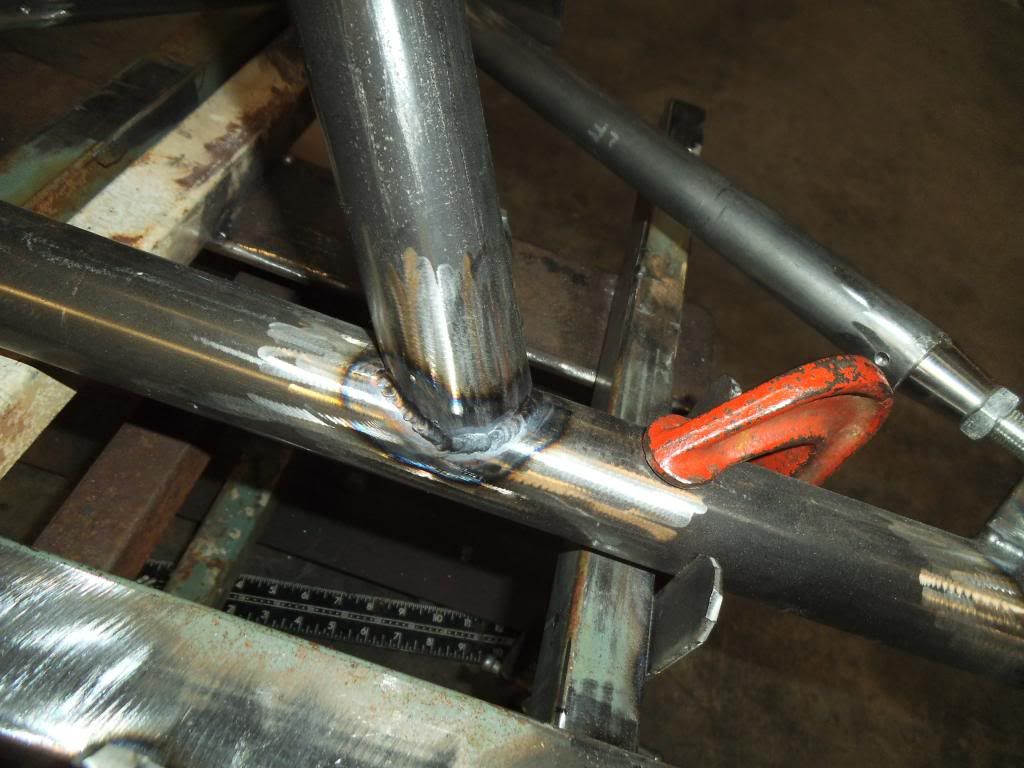
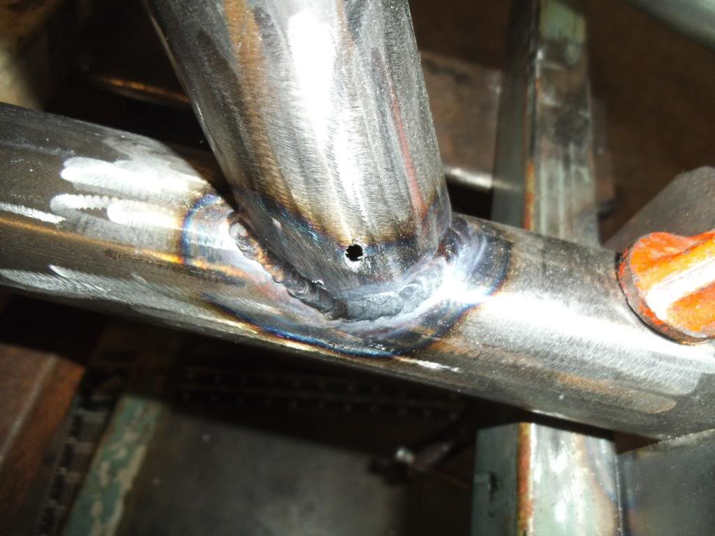
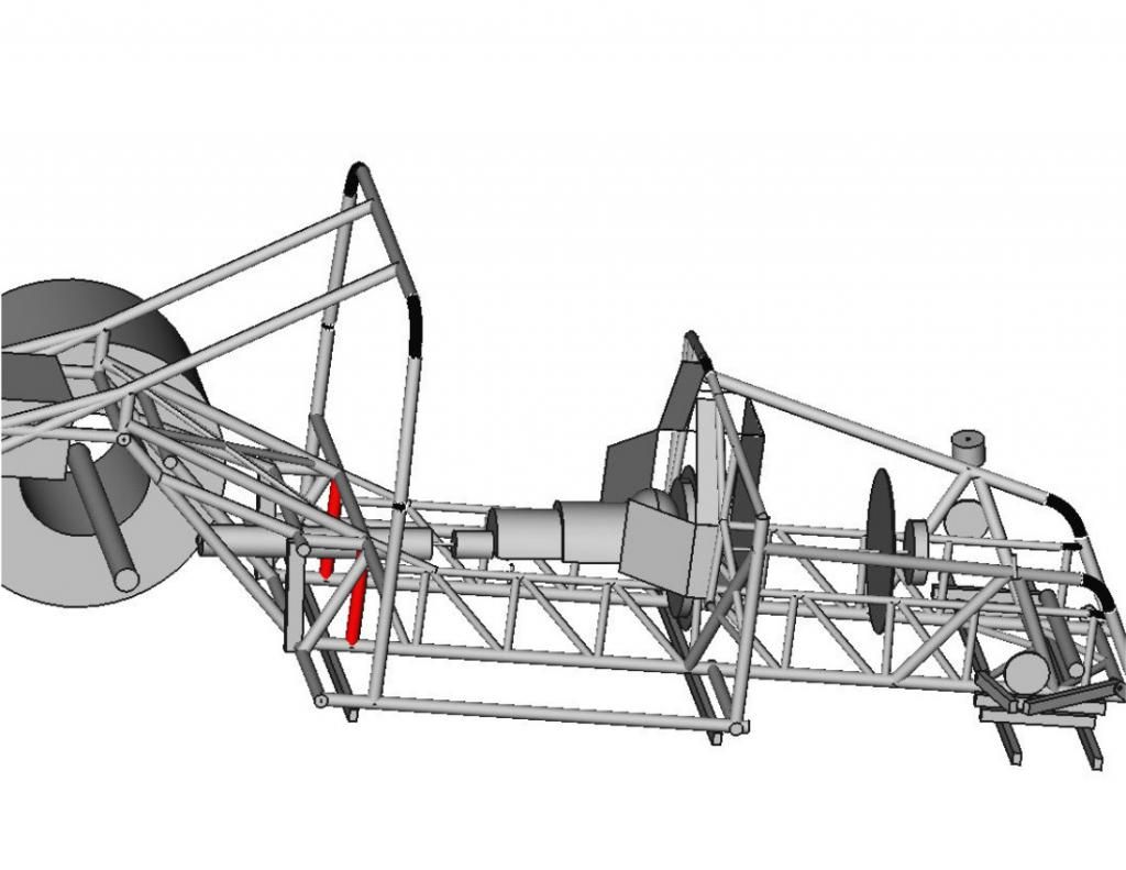
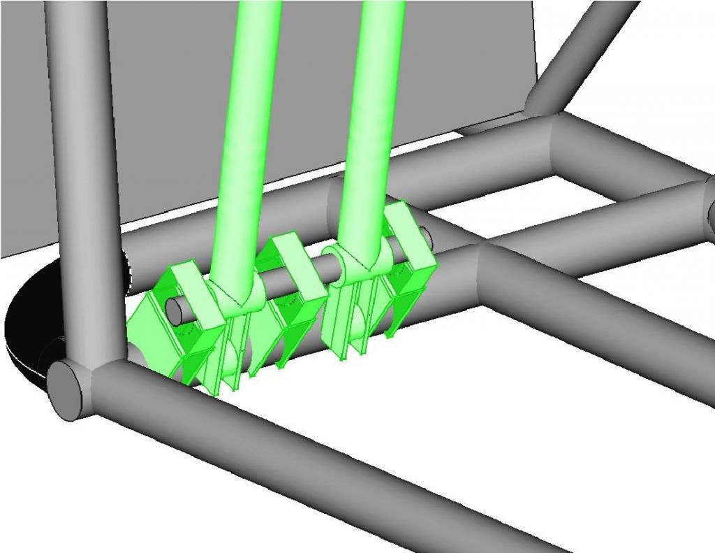
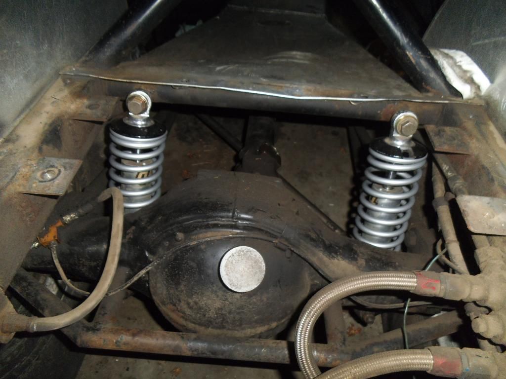
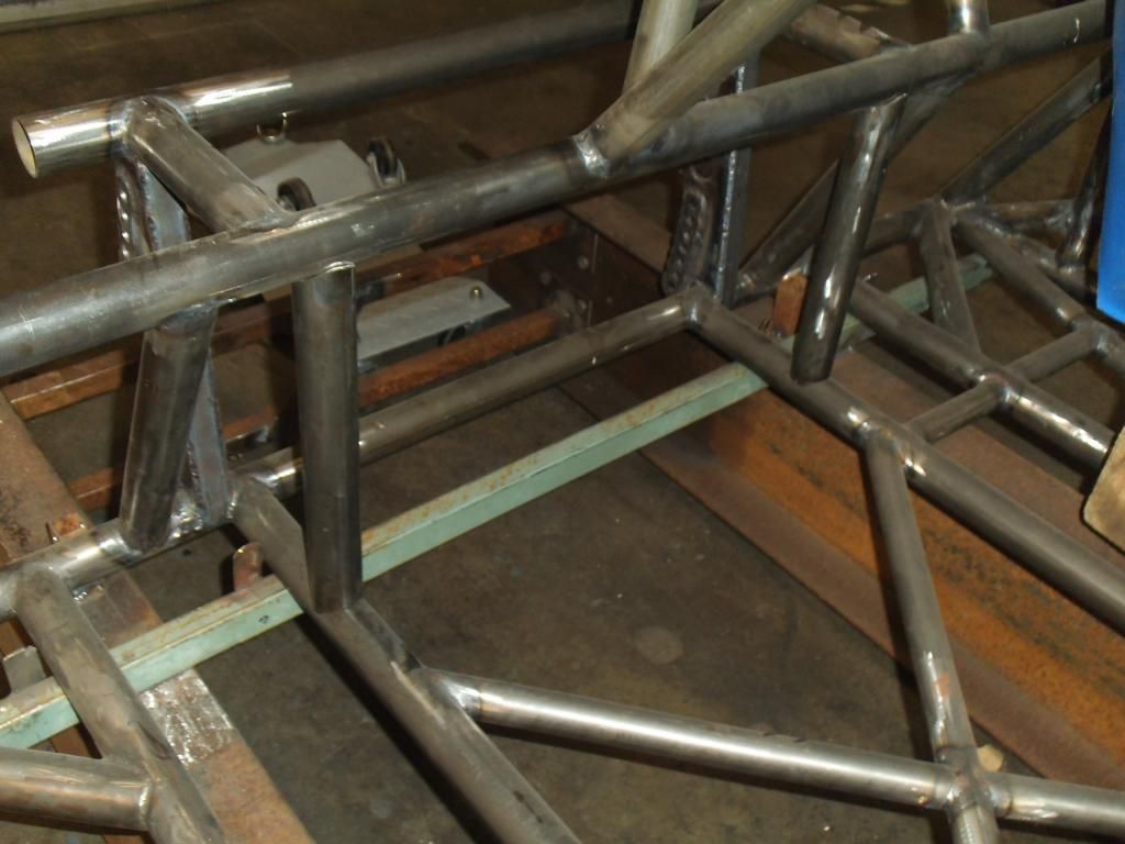
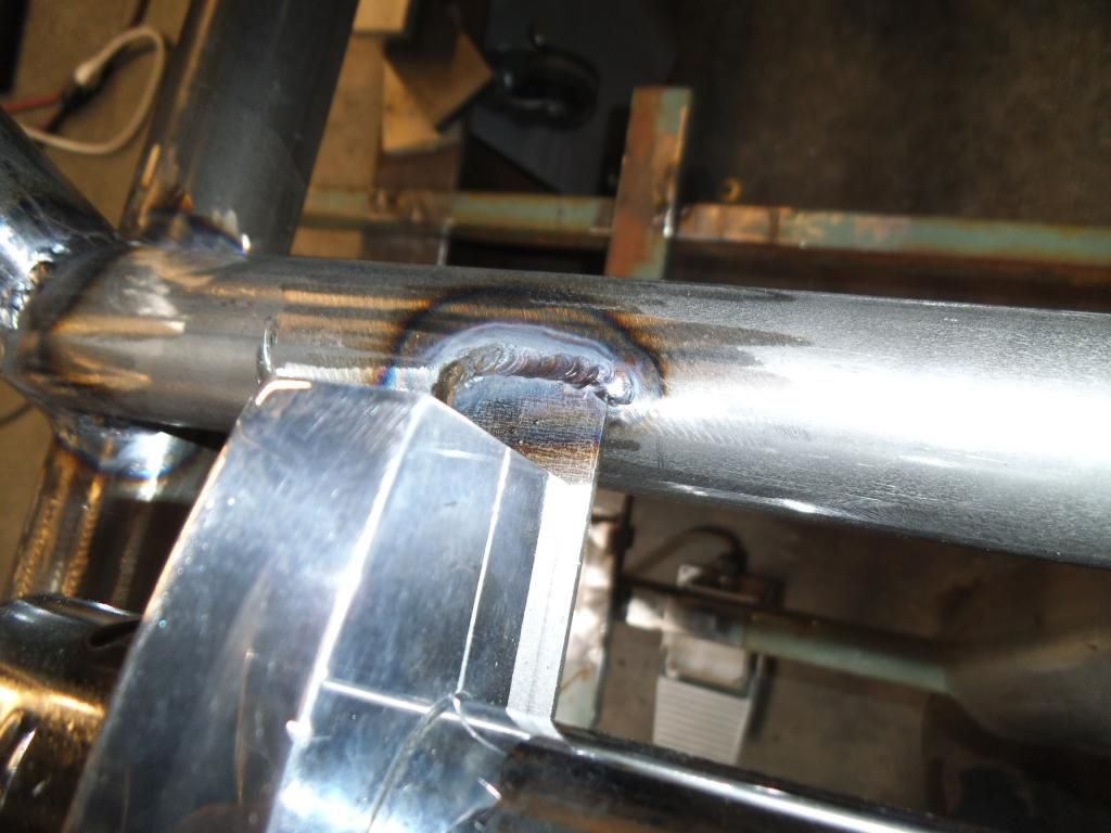
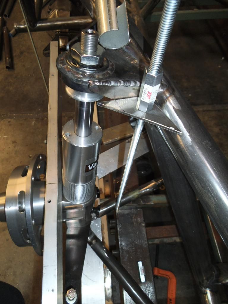
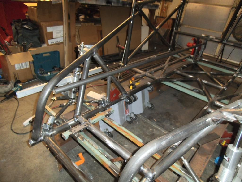
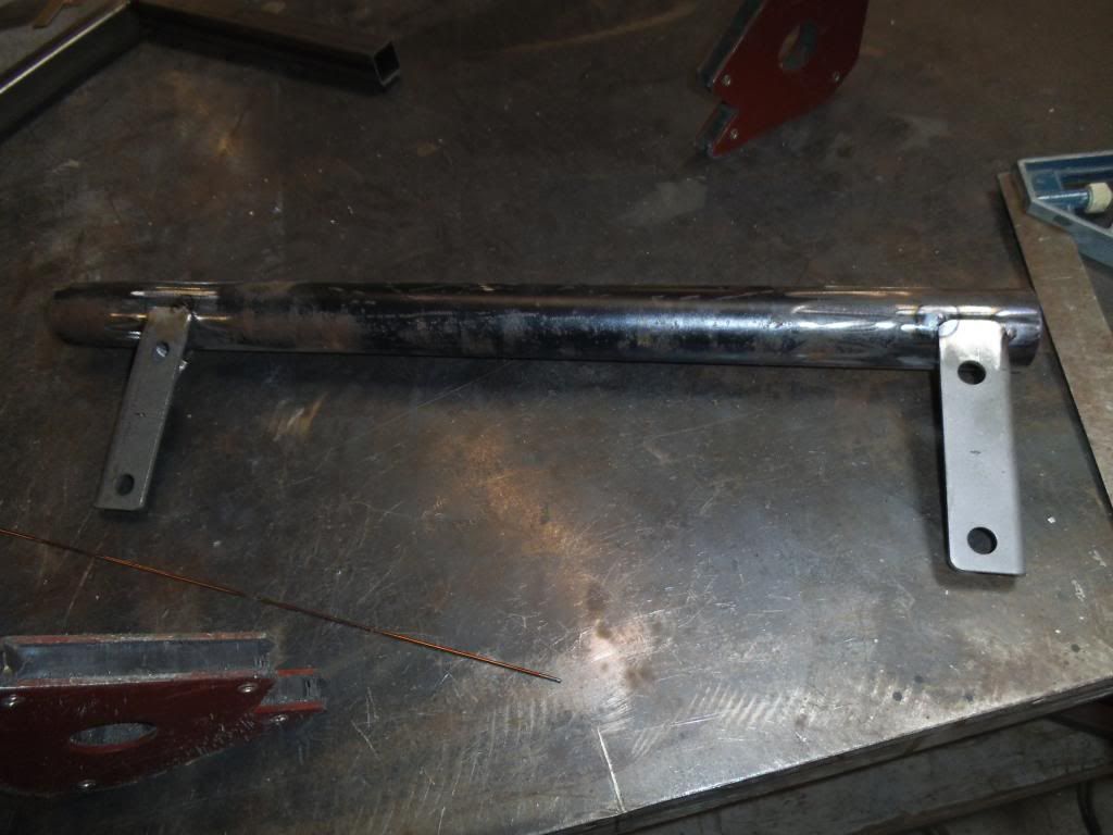
After filing tons of reports, I went back to the chassis and quadruple checked positions on everything, thenI finish-welded the left side strut support bar:
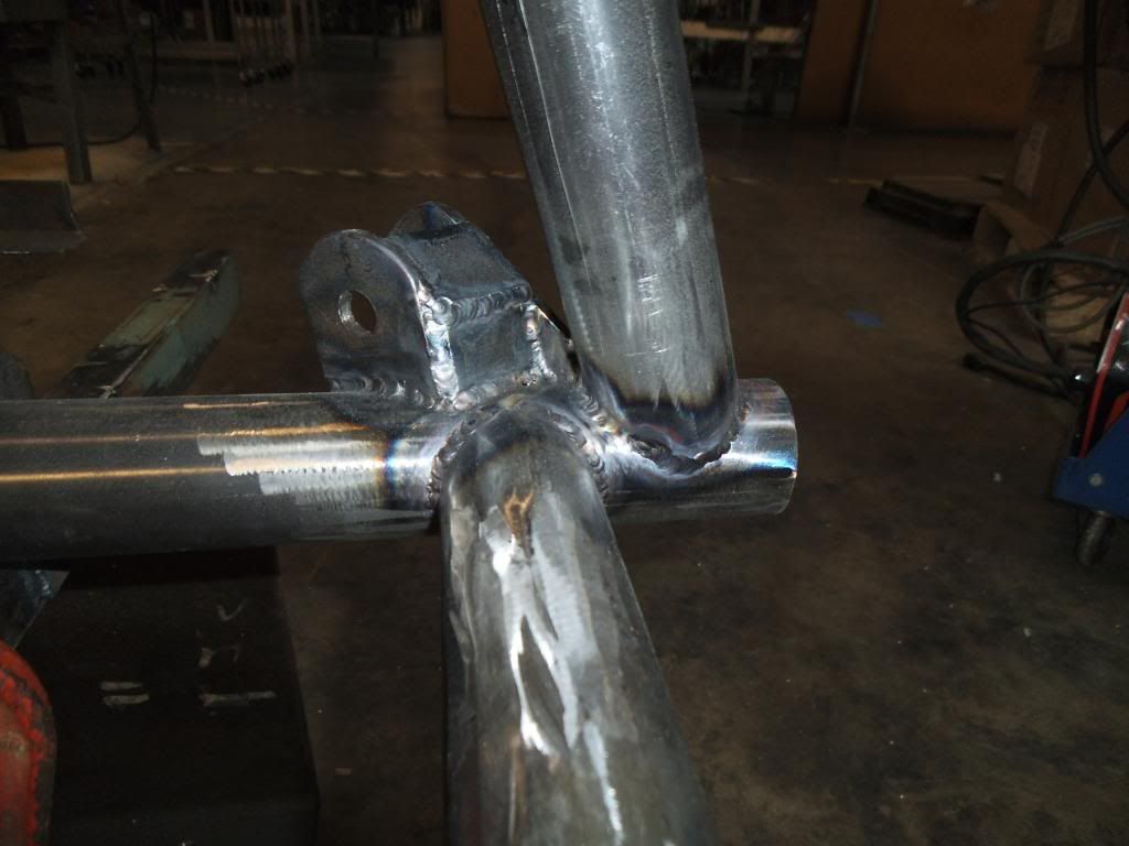
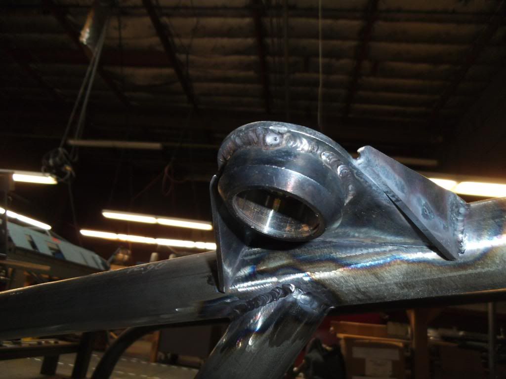
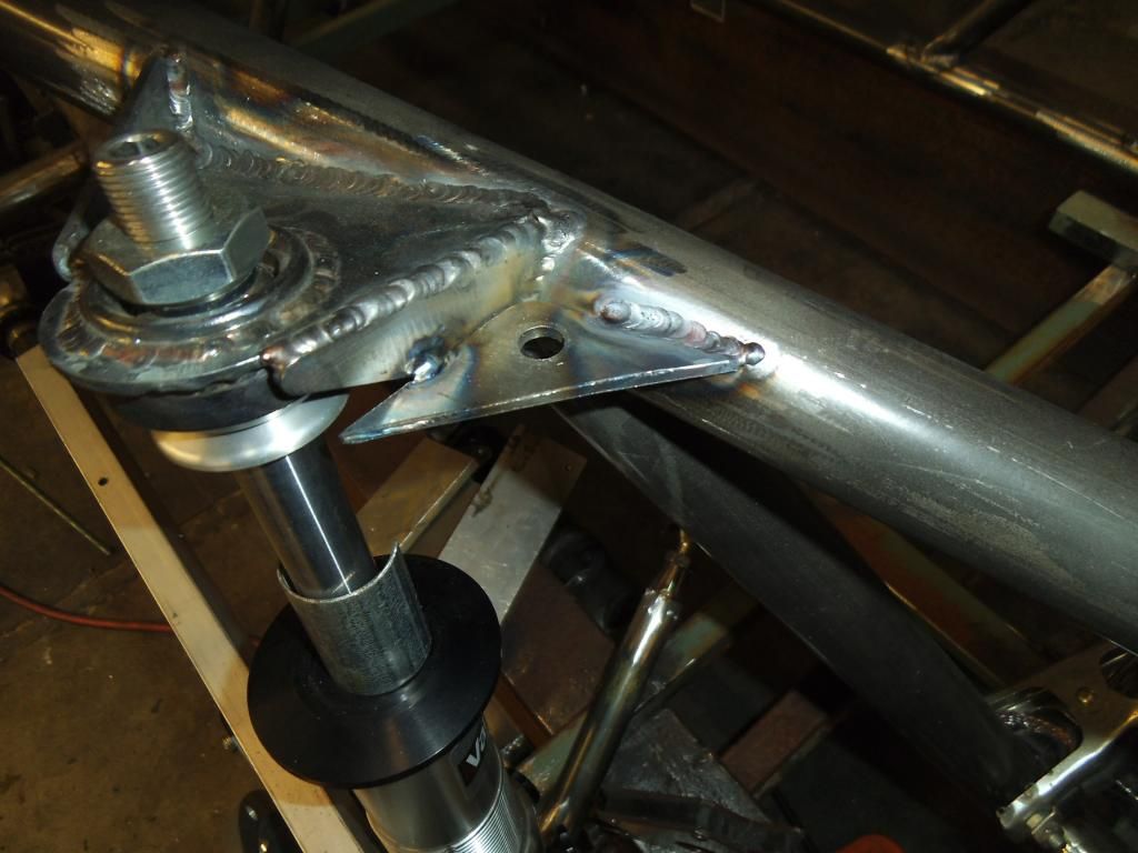
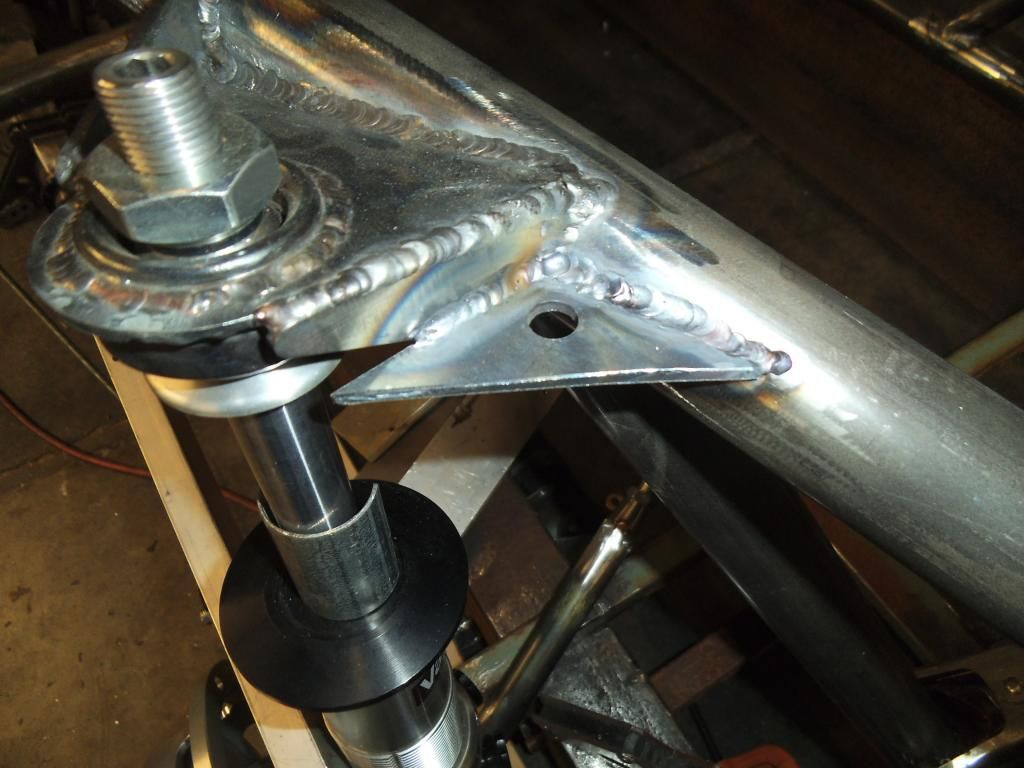
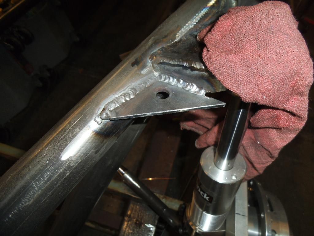
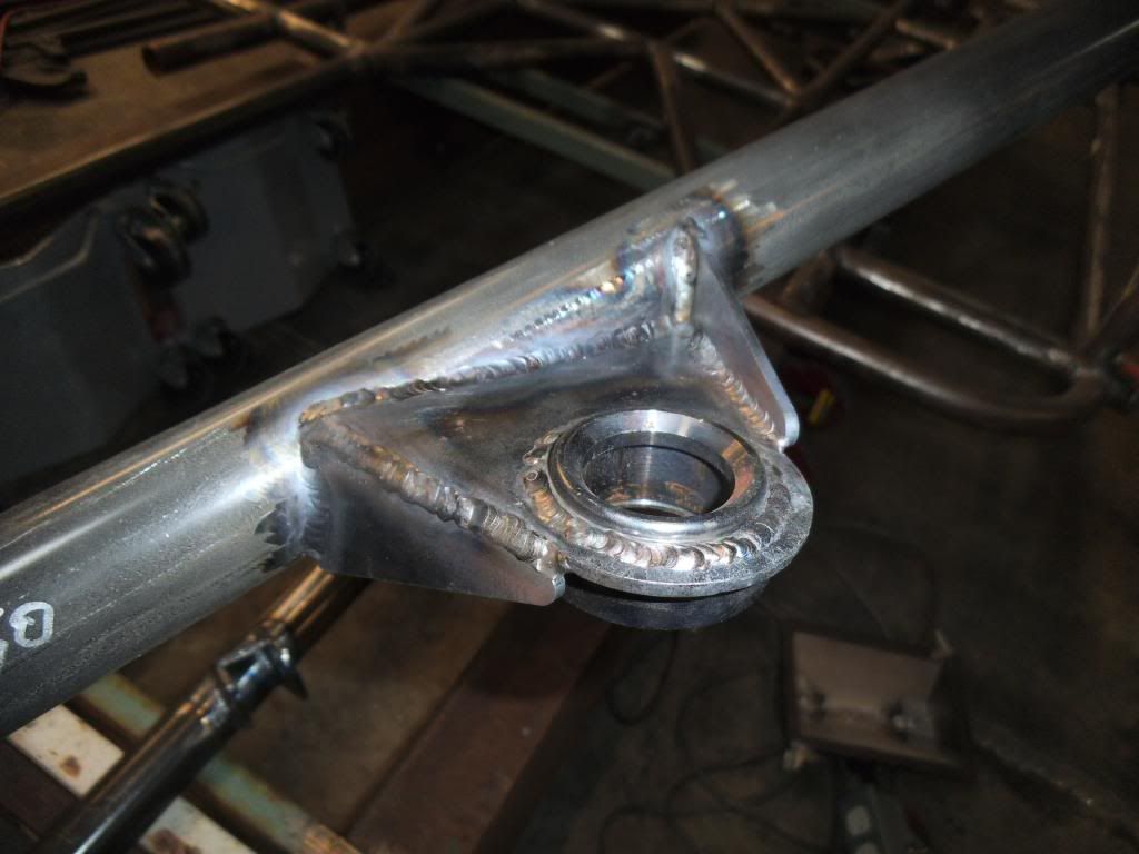
Next up I welded the left upper strut mount with its gussets:
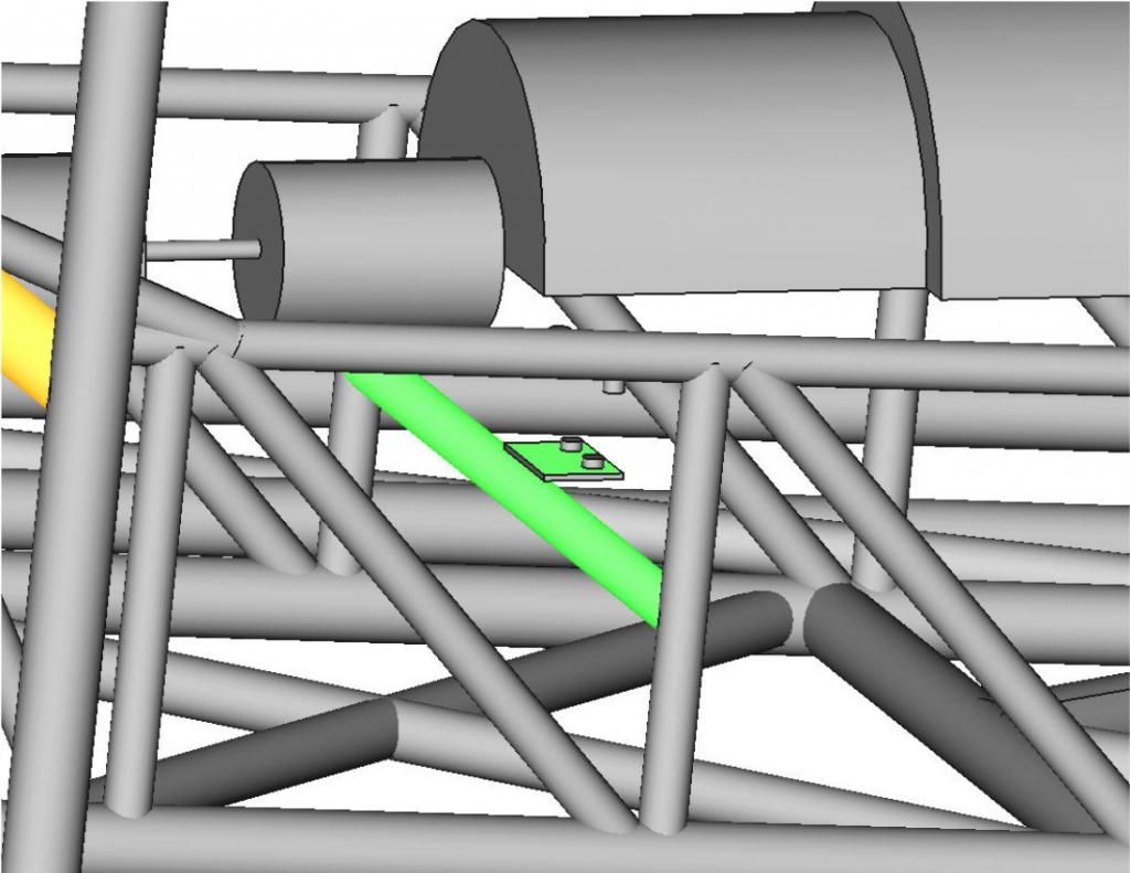
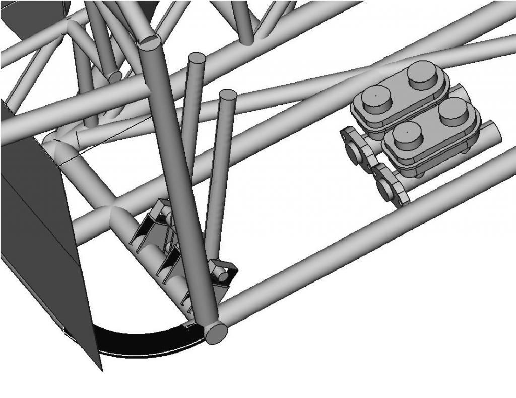
The plans from Chassisworks called for the crossmember for mounting the steering rack to be about 1.5" higher than the bottom main chassis tubes, so I couldn't just tie between those tubes like the front crossmember I previously installed.
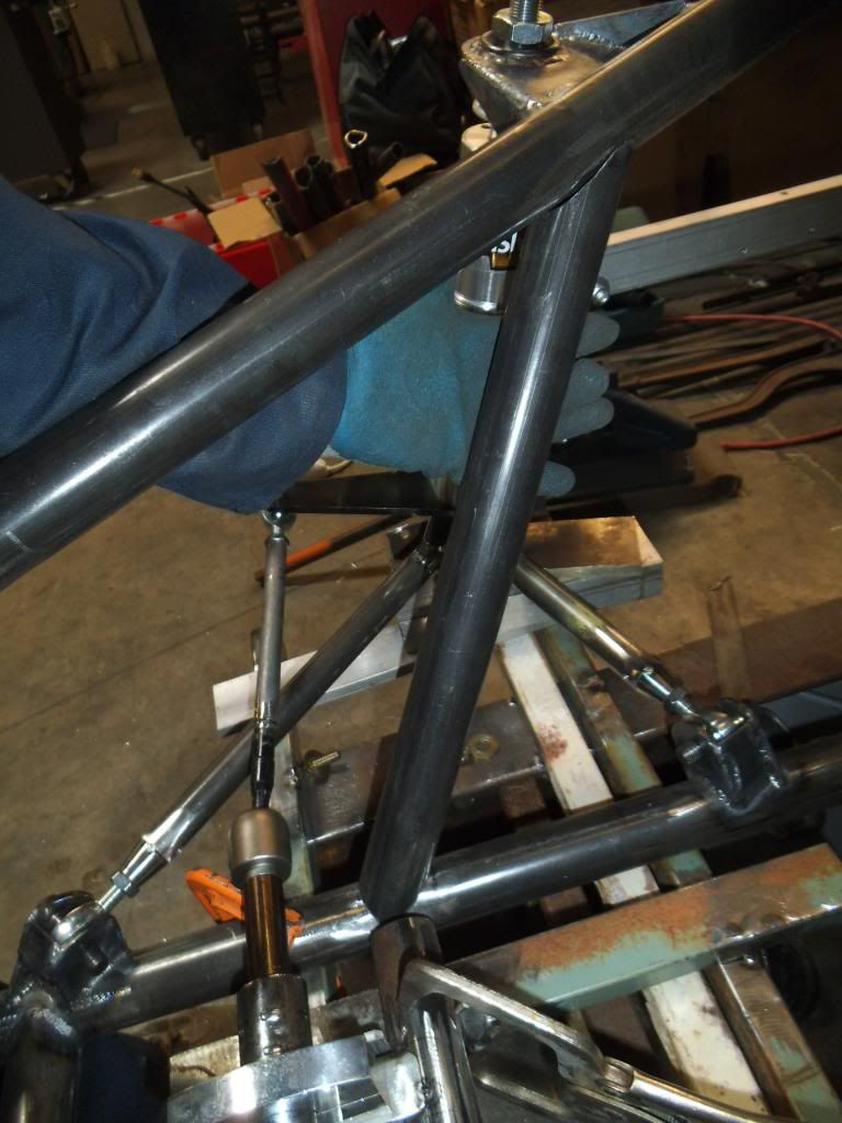
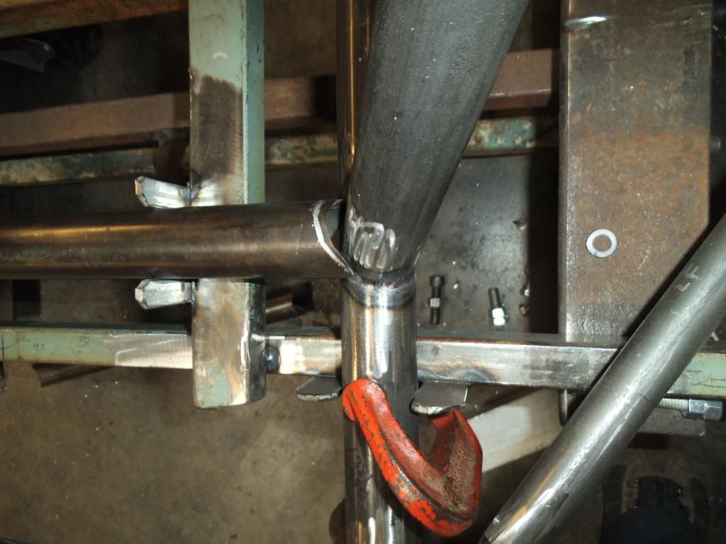
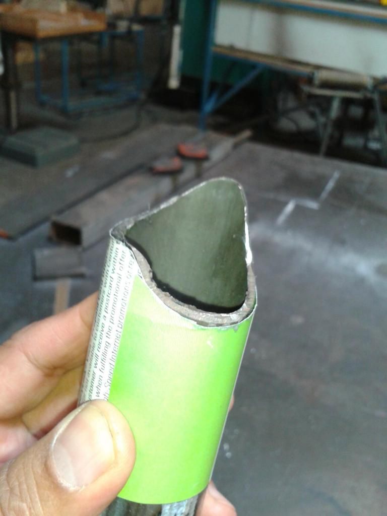
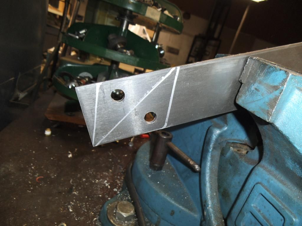
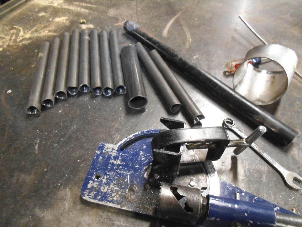
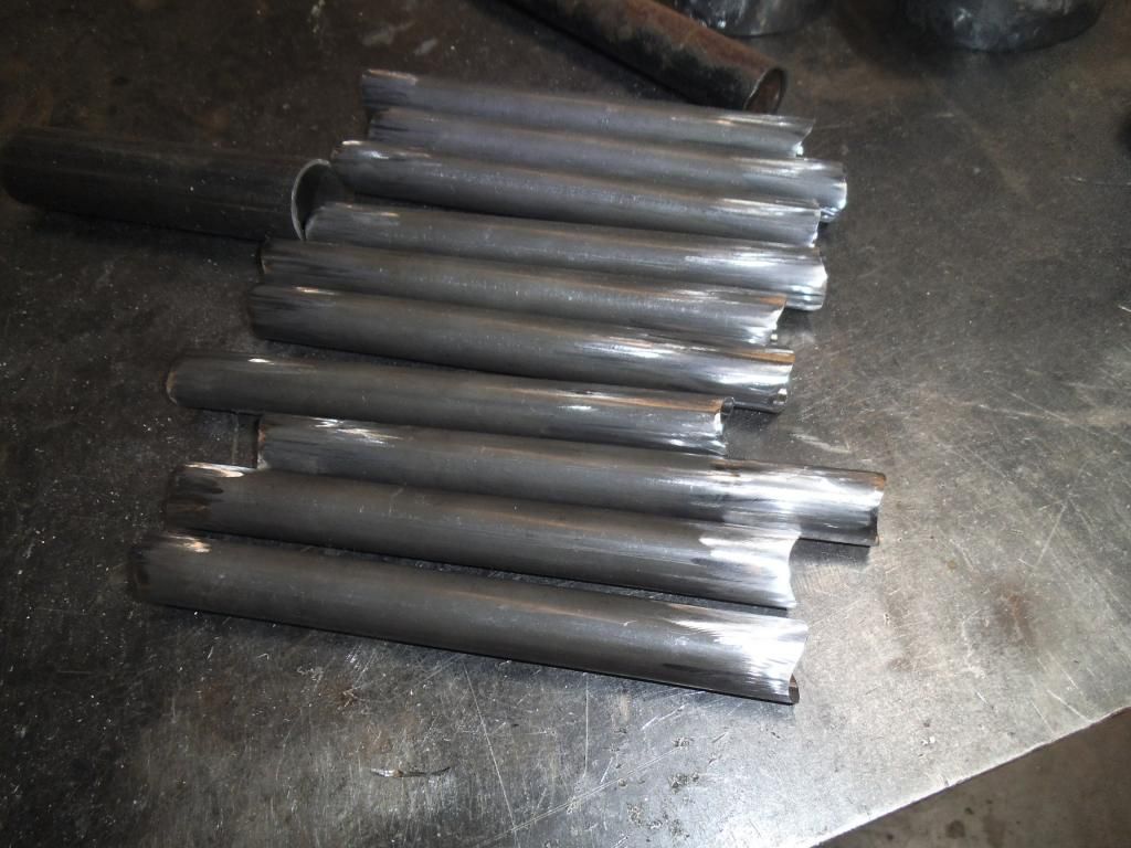
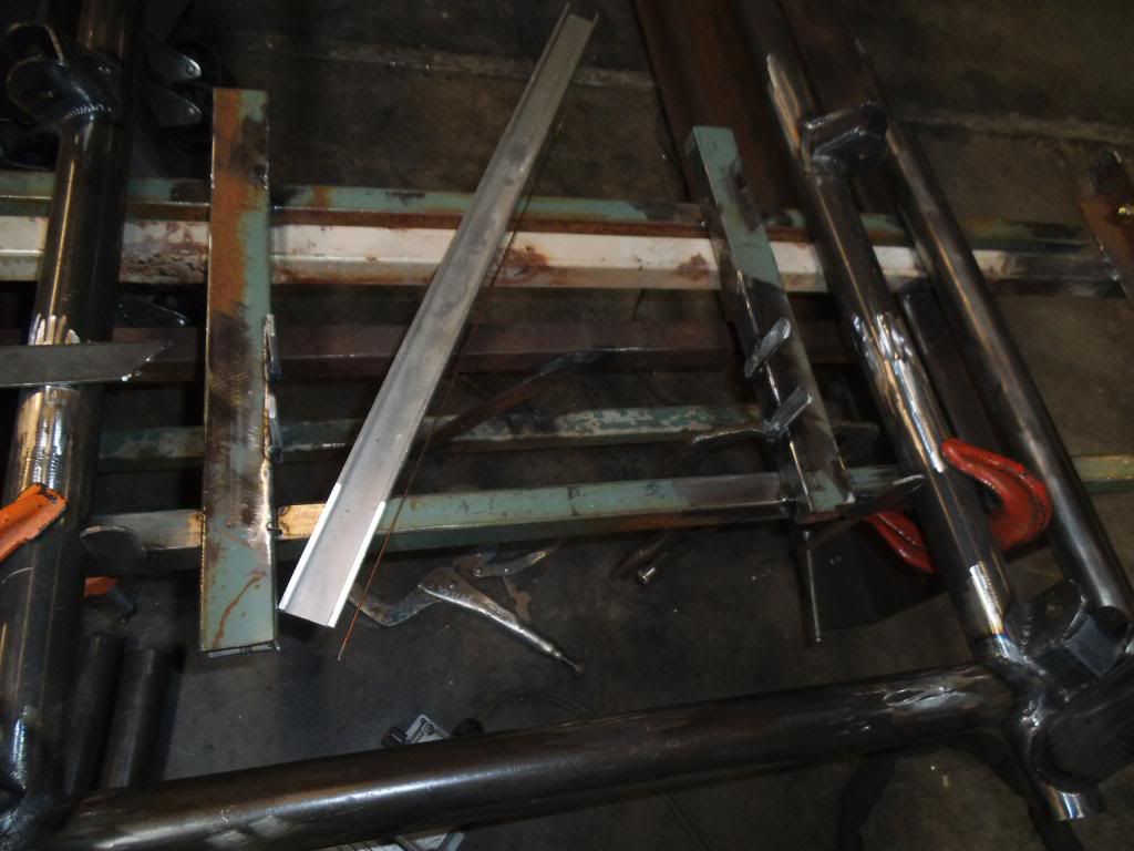
My plan was to add a couple of angled braces from the main frame rails to the strut support tubes, both to reinforce the strut mounts, and to give me a spot to tie the steering crossmember to. Unfortunately the strut tube and the main frame rail are at a compound angle to one another, so it is VERY difficult to fit the tube to both sides. I managed to notch the first tube a little too far, and had to start over. Good thing I have some extra tubing!
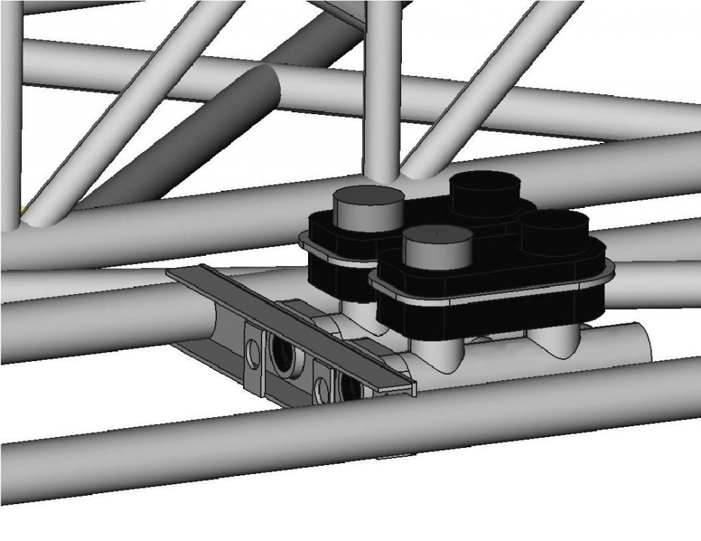
After I test fit that tube I suddenly realized that even a slight change in the position of the steering crossmember would change the length & angles on this tube! I decided to fixture up the position of the steering crossmember to be sure.
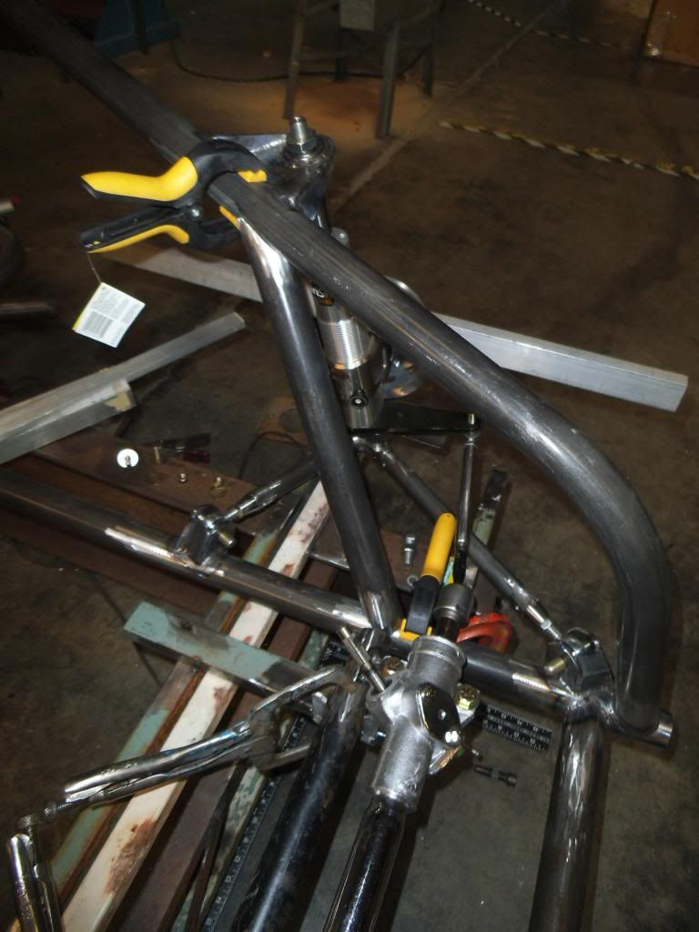
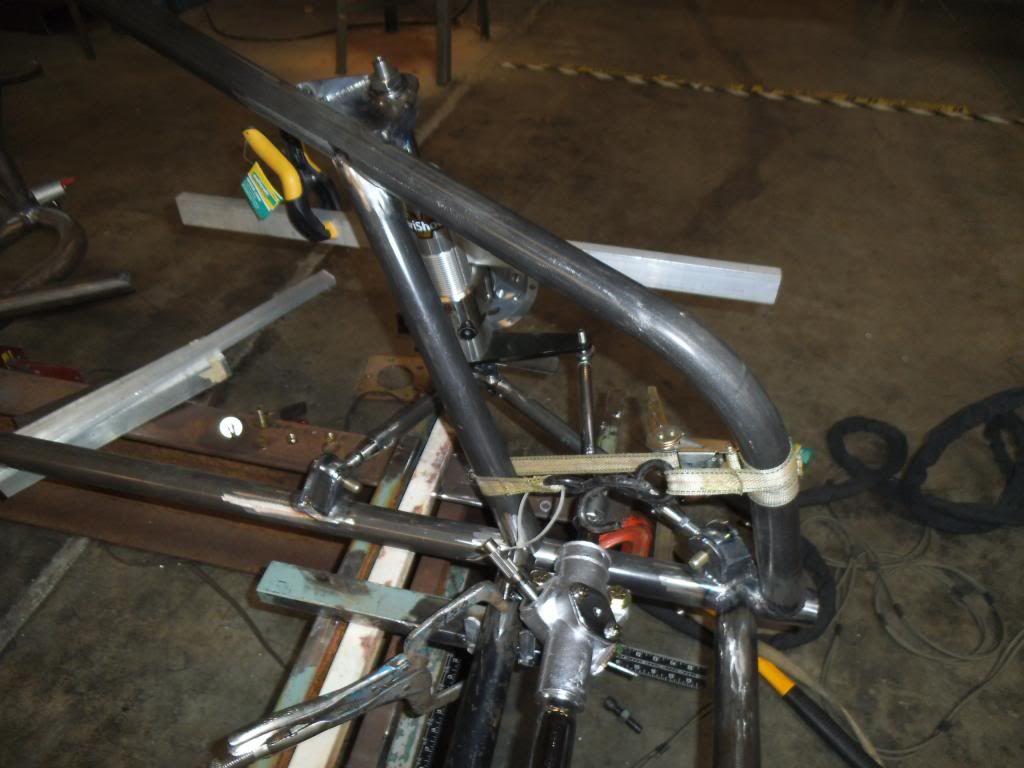
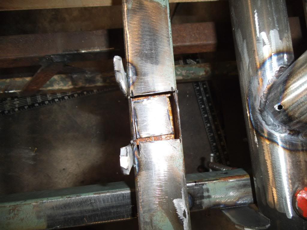
As I was starting to test fit the steering crossmember I realized that since the bottom of it was just below the top of the main frame rails, it would require a double notch on each side.
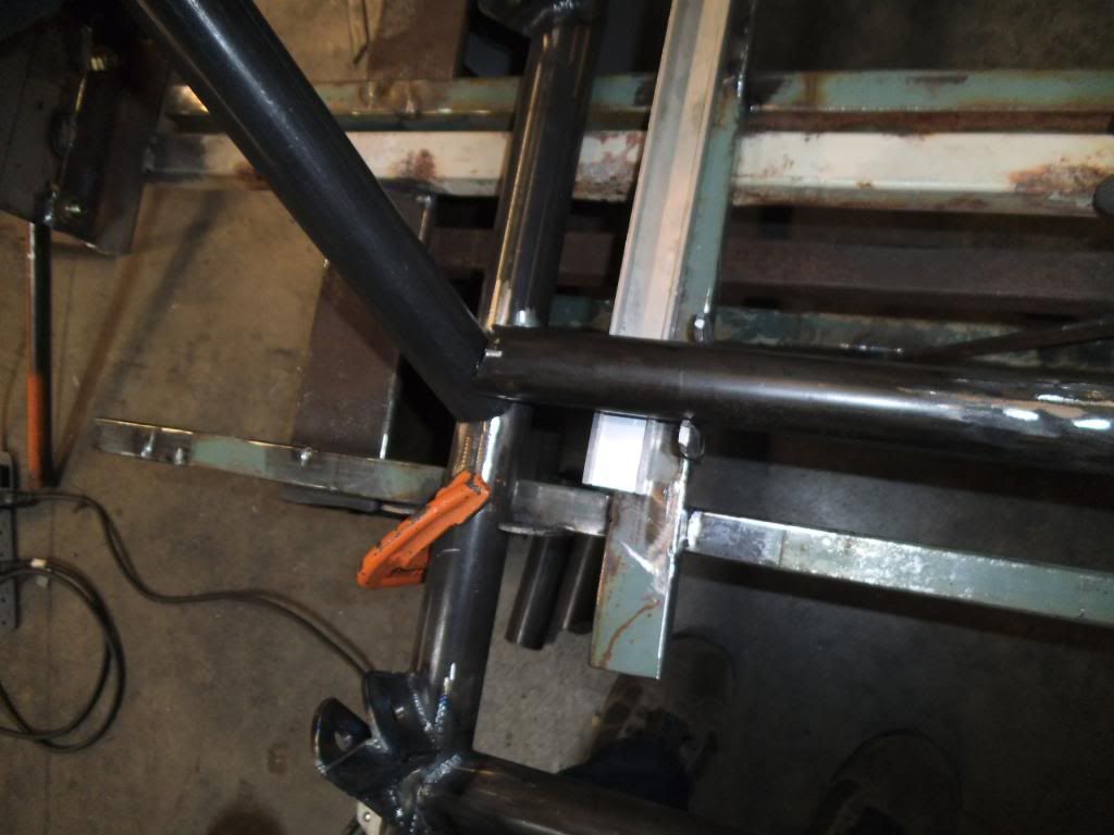
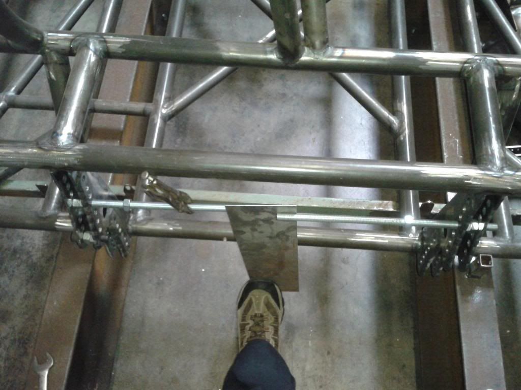
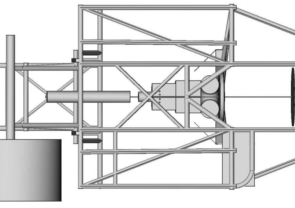
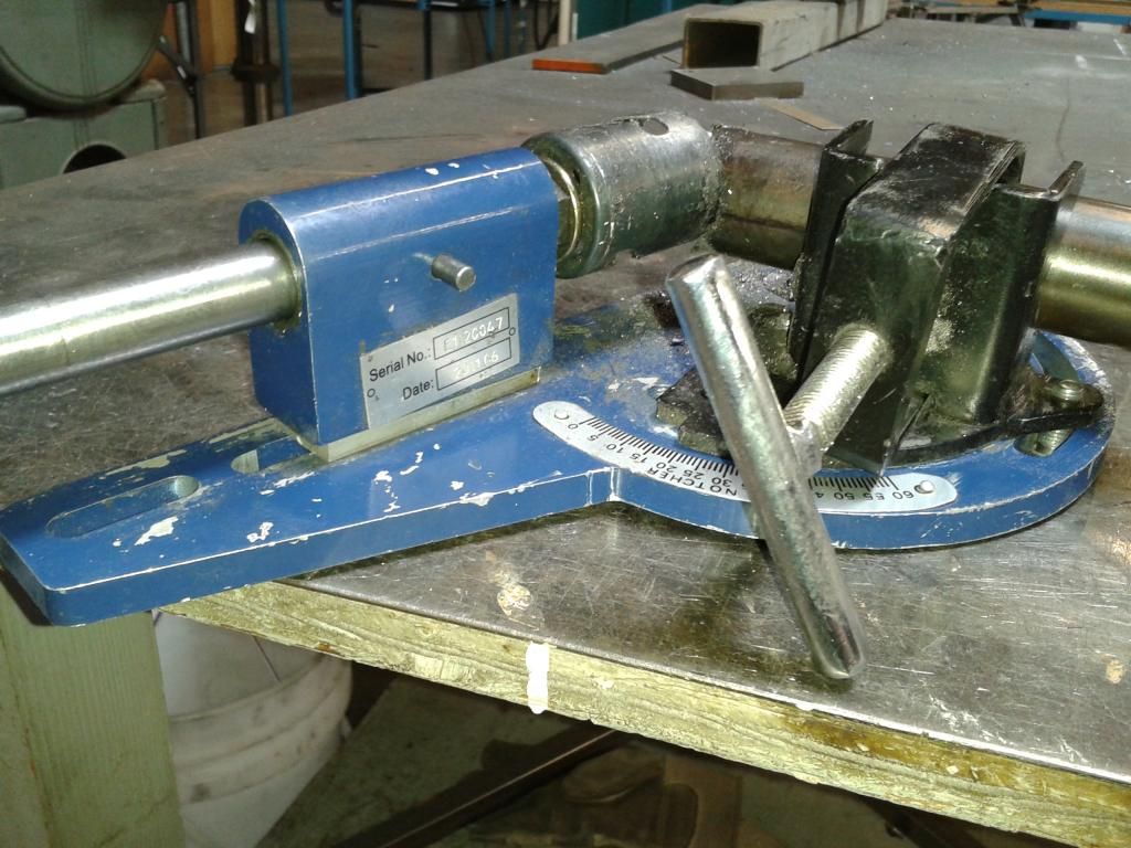
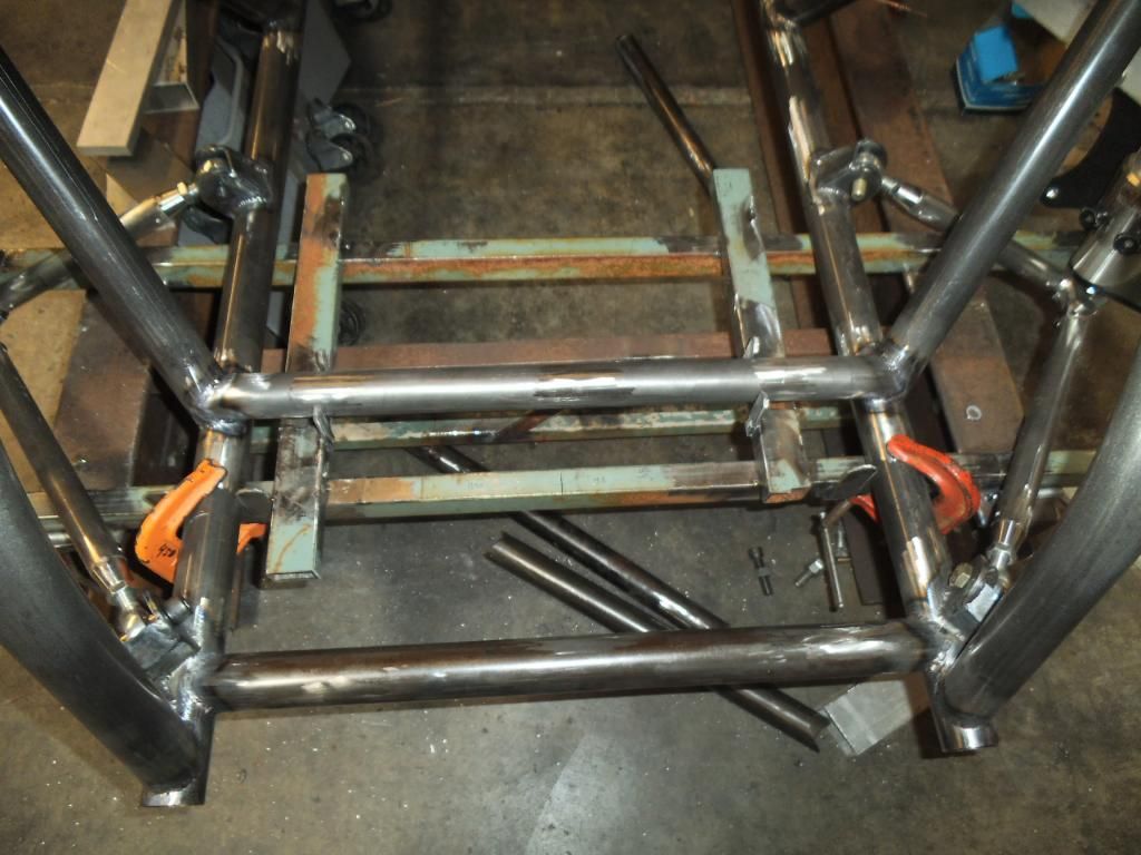
Since all of those dimensions and angles would change with a slight change in position, I used a shorter piece to make a temporary steering crossmember, so I could make sure the steering rack position was perfect.
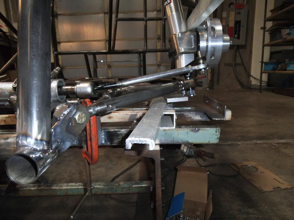
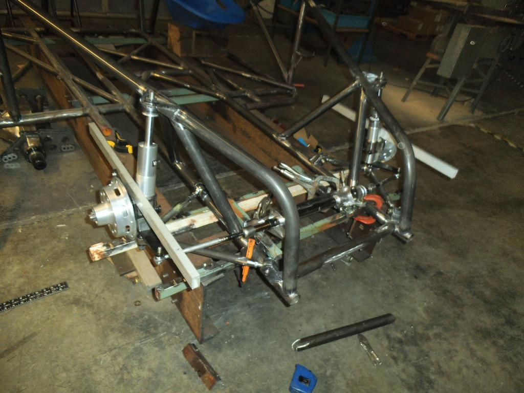
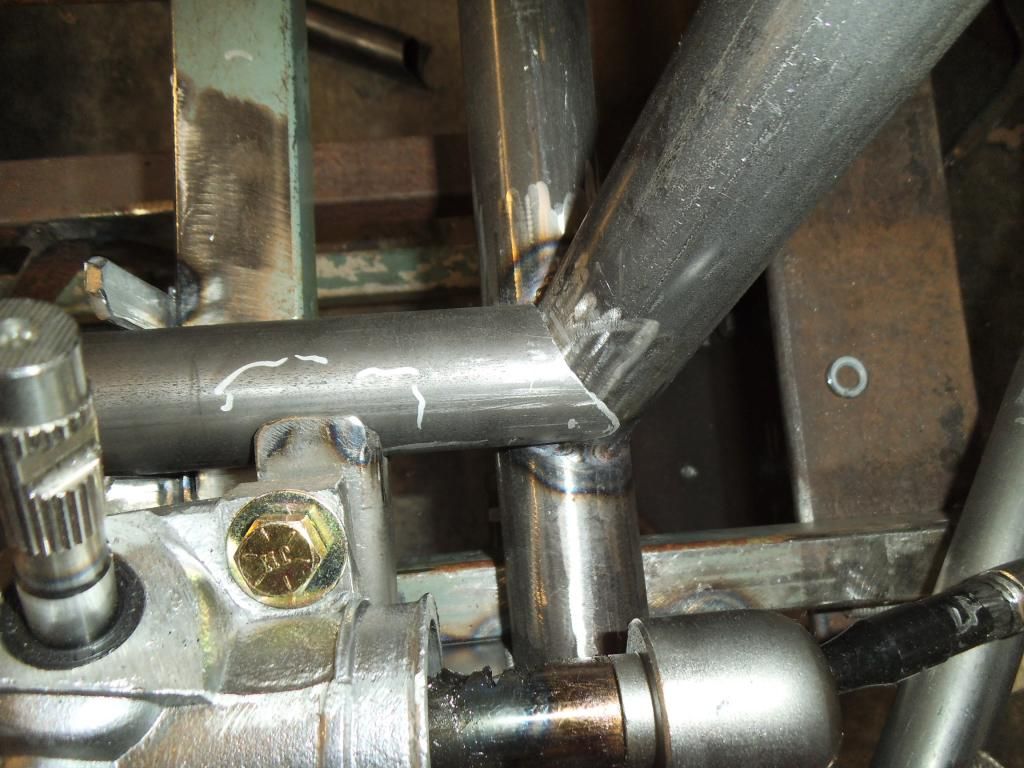
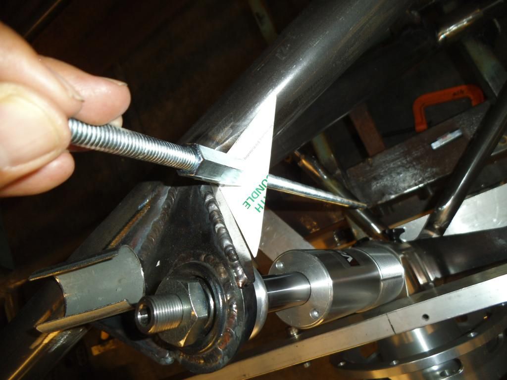
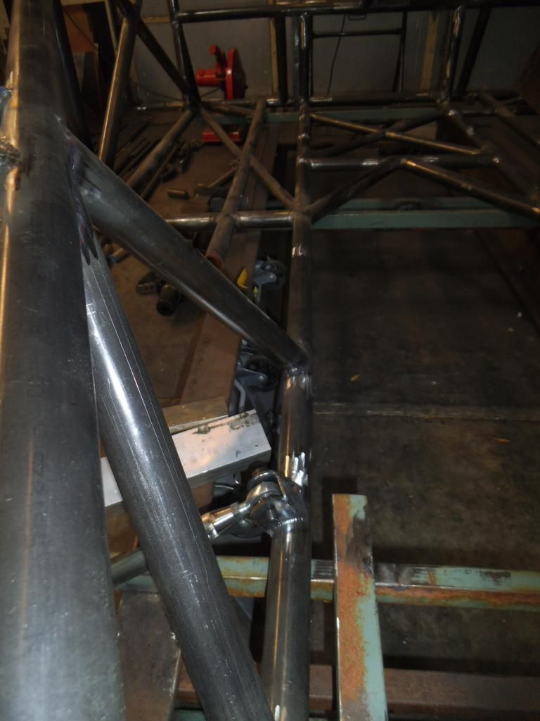
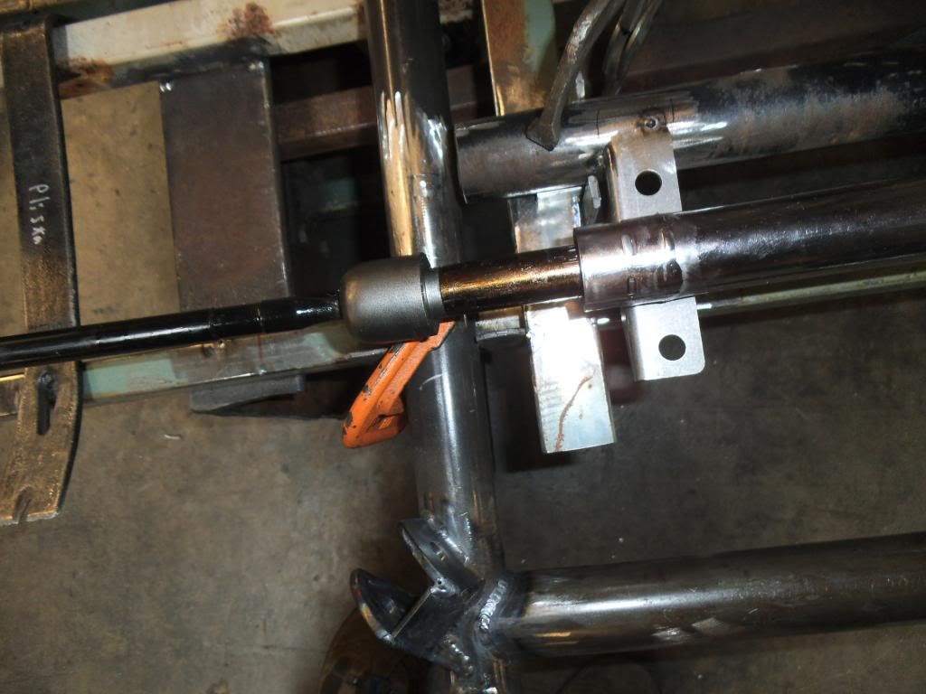
I clamped it into place on my previously added jig fixture:

At this point I was relieved that I had done all of this as a mock-up, as the dimensions for the steering mount placed one side too far outboard, where the clamp would hit a bulge in the rack that was there to hold the boot:

I remember the Chassisworks tech guy telling me that they don't make the steering racks themselves, and it has been getting harder and harder to find a place to build them. It appears their current supplier has the dimensions a little off from the original Pinto application that used these.
Now for a little boring sidebar on steering geometry:
The most critical part of all of this is eliminating what is known as "bump steer", you need to make sure the front tires do NOT change direction even the slightest bit as the suspension goes through its full articulation. In order to accomplish this the pivot point on the steering needs to be perfectly aligned with the pivot point on the lower control arms, and the height such that the steering tie rods are parallel to the lower control arms.
I decided to pull both boots so I could see for sure where the pivot points were. Sure enough, even with the steering rack centered as far as its travel, I needed to move the whole thing 0.5" to the side (in addition to moving the clamp mount as mentioned above).
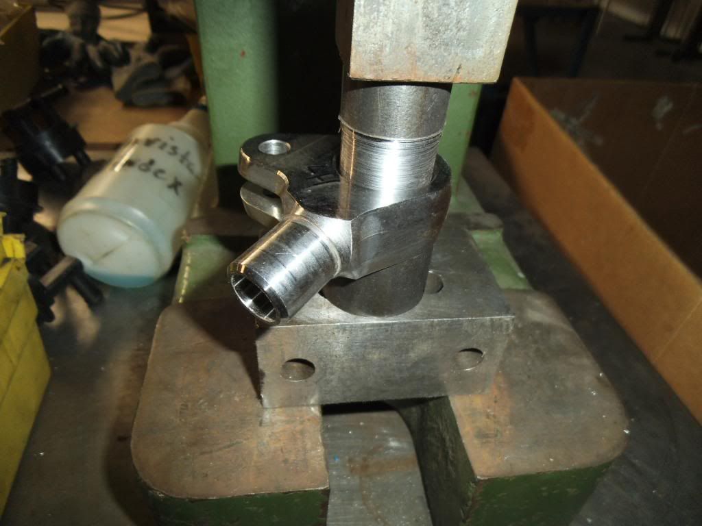
At this point I really needed the control arm & strut assemblies together so I could check the aforementioned parallel requirement. I pressed the bearings out of the lower control arm ends:
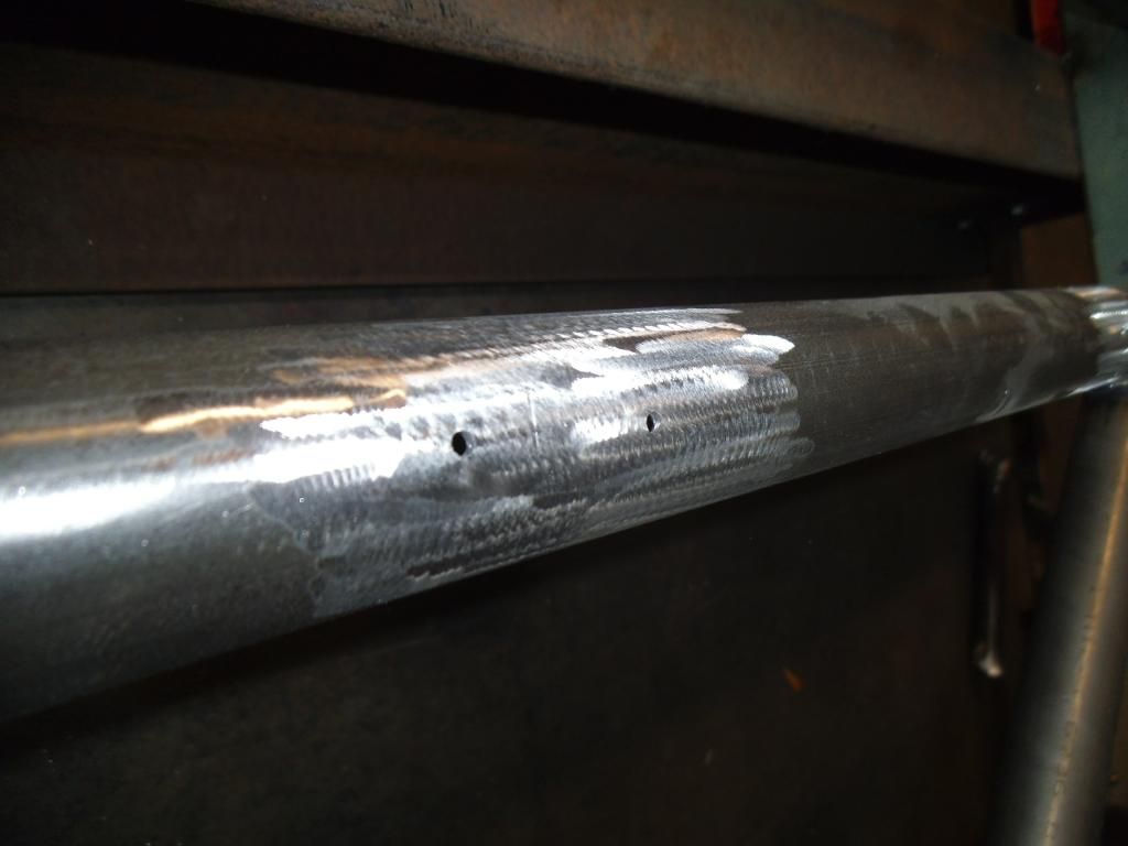
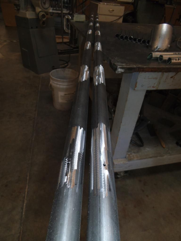
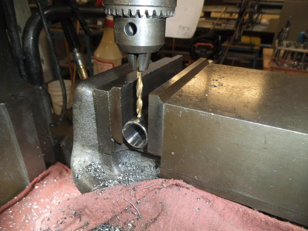
The tubes needed to be drilled for rosette welds:
I just tack welded them together for now, in case I need some adjustment in length. While there is adjustment in the rod ends, I want to start out with them right in the middle of their adjustment!

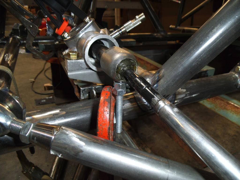
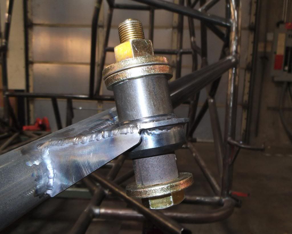
As I went to assemble everything, I pressed the spherical bearings back into the A-arms without too much effort, but when I went to press the bearings into the upper strut mounts I found that the weld distortion made it so hard that I was bending the biggest C-clamp I had! This was even after freezing the bearings! I was prepared to heat up the sockets as well, but decided to come up with something different for pressing the bearings in. I ended up using some specific cut sections of tubing with a 3/4" fine thread grade 8 bolt, which had the secondary effect of forcing everything into alignment as it pressed it together. No need for heat as this pulled the bearing right into place.
I used shims between the control arm and the jig to hold the strut assemblies exactly at ride height, then measured off where the updated tie rod tubes and the original tie rod shafts needed to be cut in order to weld them together.
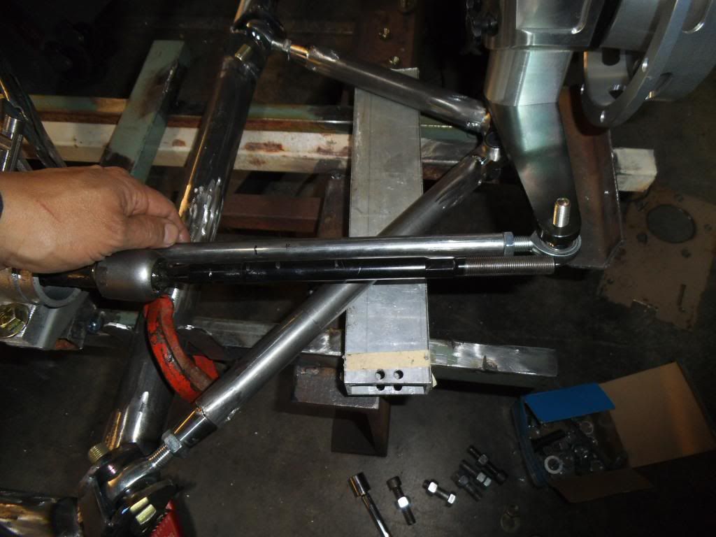
I learned that this was another area where the reproduction Pinto rack was different than the factory ones. This one used a MUCH larger diameter tie rod shaft than the originals, and the originals normally fit into the tubes I am supposed to weld them to.
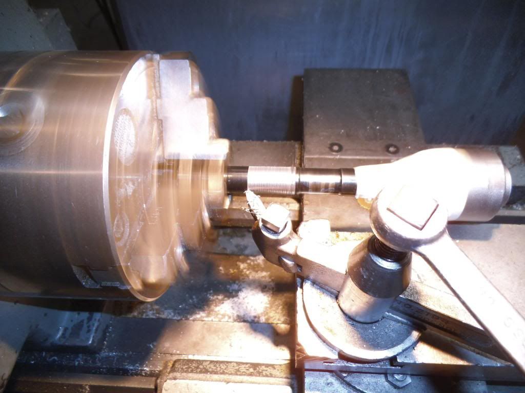
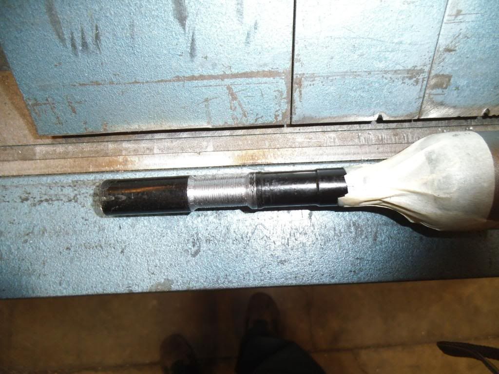
I made the cuts, counterbored the tubes (they were counterbored for their ends, but needed to be rebored since I was cutting them so short), then used the lathe to cut down the tie rod shaft diameter to where it would fit:
Now I should be able to tack everything together and verify that the steering geometry holds up throughout the suspension travel.
I swear there is always something that keeps me from spending time on this build. In this case I lost a few days to clearing up a case of ID theft! I went to file my taxes and found out that someone had already filed a fraudulent return using my information. It turns out that a large percentage of people who volunteer for Catholic schools in our part of the country had this happen, apparently by someone in the company they used for the legally required background checks. Too bad they couldn't have paid the tax bill I actually had due!
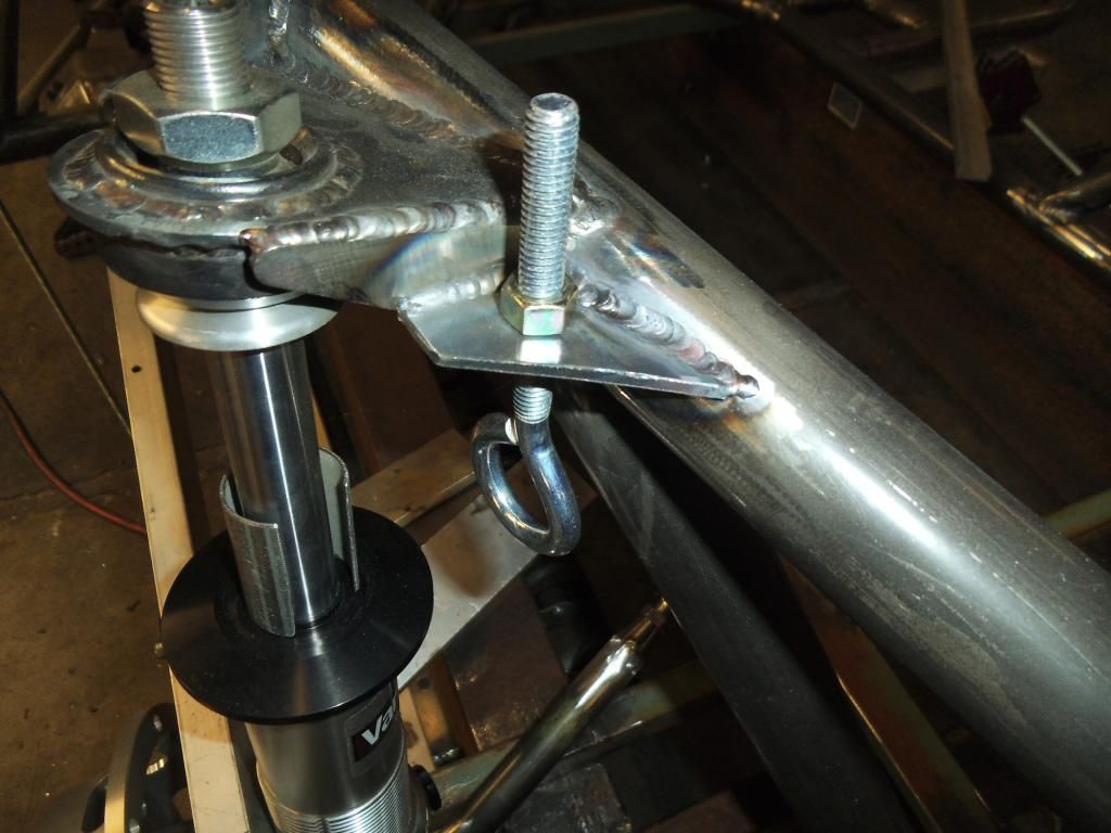
After filing tons of reports, I went back to the chassis and quadruple checked positions on everything, thenI finish-welded the left side strut support bar:
Next up I welded the left upper strut mount with its gussets:
The plans from Chassisworks called for the crossmember for mounting the steering rack to be about 1.5" higher than the bottom main chassis tubes, so I couldn't just tie between those tubes like the front crossmember I previously installed.
My plan was to add a couple of angled braces from the main frame rails to the strut support tubes, both to reinforce the strut mounts, and to give me a spot to tie the steering crossmember to. Unfortunately the strut tube and the main frame rail are at a compound angle to one another, so it is VERY difficult to fit the tube to both sides. I managed to notch the first tube a little too far, and had to start over. Good thing I have some extra tubing!
After I test fit that tube I suddenly realized that even a slight change in the position of the steering crossmember would change the length & angles on this tube! I decided to fixture up the position of the steering crossmember to be sure.
As I was starting to test fit the steering crossmember I realized that since the bottom of it was just below the top of the main frame rails, it would require a double notch on each side.
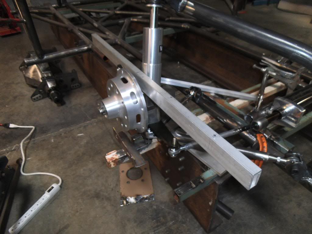
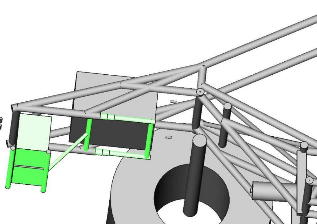
Since all of those dimensions and angles would change with a slight change in position, I used a shorter piece to make a temporary steering crossmember, so I could make sure the steering rack position was perfect.
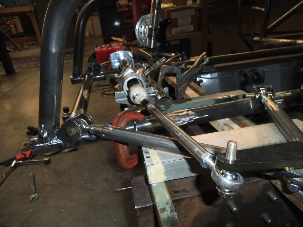
I clamped it into place on my previously added jig fixture:
At this point I was relieved that I had done all of this as a mock-up, as the dimensions for the steering mount placed one side too far outboard, where the clamp would hit a bulge in the rack that was there to hold the boot:
I remember the Chassisworks tech guy telling me that they don't make the steering racks themselves, and it has been getting harder and harder to find a place to build them. It appears their current supplier has the dimensions a little off from the original Pinto application that used these.
Now for a little boring sidebar on steering geometry:
The most critical part of all of this is eliminating what is known as "bump steer", you need to make sure the front tires do NOT change direction even the slightest bit as the suspension goes through its full articulation. In order to accomplish this the pivot point on the steering needs to be perfectly aligned with the pivot point on the lower control arms, and the height such that the steering tie rods are parallel to the lower control arms.
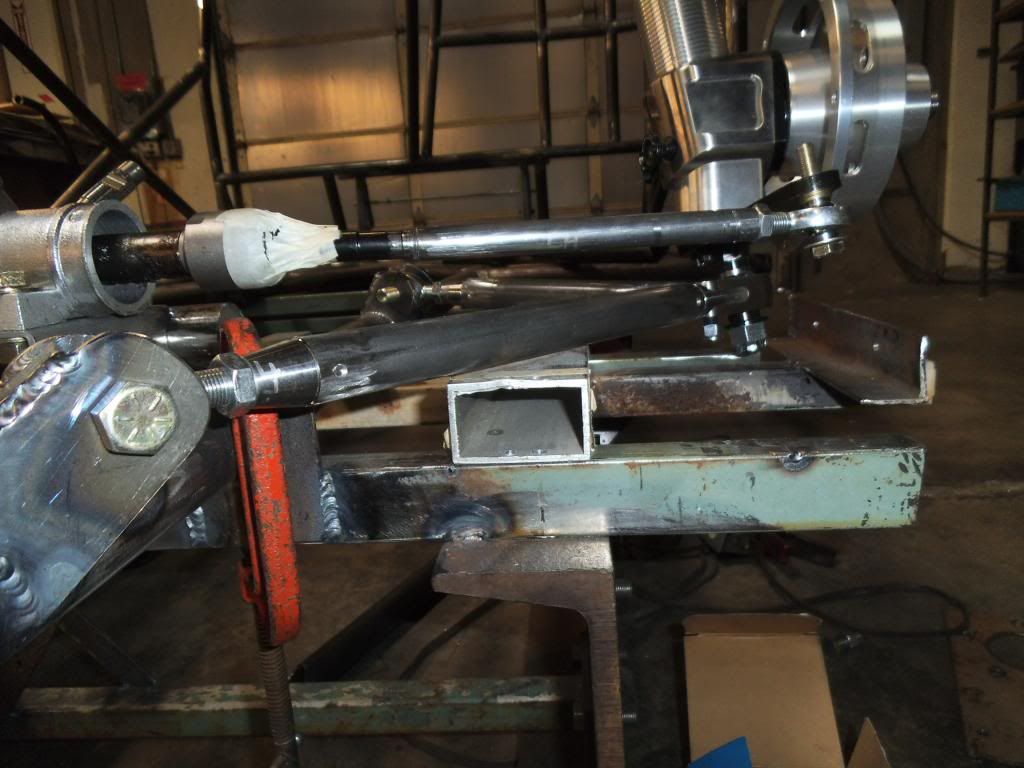
I decided to pull both boots so I could see for sure where the pivot points were. Sure enough, even with the steering rack centered as far as its travel, I needed to move the whole thing 0.5" to the side (in addition to moving the clamp mount as mentioned above).
At this point I really needed the control arm & strut assemblies together so I could check the aforementioned parallel requirement. I pressed the bearings out of the lower control arm ends:
The tubes needed to be drilled for rosette welds:
I just tack welded them together for now, in case I need some adjustment in length. While there is adjustment in the rod ends, I want to start out with them right in the middle of their adjustment!
As I went to assemble everything, I pressed the spherical bearings back into the A-arms without too much effort, but when I went to press the bearings into the upper strut mounts I found that the weld distortion made it so hard that I was bending the biggest C-clamp I had! This was even after freezing the bearings! I was prepared to heat up the sockets as well, but decided to come up with something different for pressing the bearings in. I ended up using some specific cut sections of tubing with a 3/4" fine thread grade 8 bolt, which had the secondary effect of forcing everything into alignment as it pressed it together. No need for heat as this pulled the bearing right into place.
I used shims between the control arm and the jig to hold the strut assemblies exactly at ride height, then measured off where the updated tie rod tubes and the original tie rod shafts needed to be cut in order to weld them together.
I learned that this was another area where the reproduction Pinto rack was different than the factory ones. This one used a MUCH larger diameter tie rod shaft than the originals, and the originals normally fit into the tubes I am supposed to weld them to.
I made the cuts, counterbored the tubes (they were counterbored for their ends, but needed to be rebored since I was cutting them so short), then used the lathe to cut down the tie rod shaft diameter to where it would fit:
Now I should be able to tack everything together and verify that the steering geometry holds up throughout the suspension travel.
")