IAT relocation mod on LLY

kidturbo

Piston Tester
Jul 21, 2010
2,320
1,082
113
Somewhere On The Ohio
www.marinemods.us
Hey guys did some searching but didn't find anything specific on this subject.

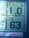
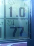
Has anyone swapped a LBZ/LMM IAT2 sensor in place of the MAF temp sensor on a LLY or older Dmax? Reason I ask, my LLY boat uses a water to air cooler and the temps under the hatch are sometimes 180F plus. After the charge cooler that might be in the 60's depending on incoming water temps.

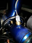
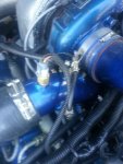
I've long ago modified the IAT tables to pretty much disregard that sensor, but would still like to monitor the true intake temps on the digital dash display. Could even be made useful again if was a true reading. Never understood the reason for a pre-turbo temp, guess someone at GM finally felt the same.. I've got plenty of spare ports in the custom Y-pipe intake, figured why not just convert it.

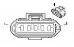
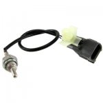
So is there anything special about the new style IAT sensors or voltage that I need to consider? And what's the correct part # ? Yes I googled for it...
 

kidturbo

Piston Tester
Jul 21, 2010
2,320
1,082
113
Somewhere On The Ohio
www.marinemods.us
Parts Update

Ok kids, here is what I've dug up so far..

The new style LBZ/LMM IAT2 sensor is no good for this project. "Temperature vs Resistance Values" between MAF mounted IAT1 and Y-pipe mounted IAT2 are not the same. There is a A/D scaling adjustment table for the IAT sensor under "System" in EFIlive, but the scale is only 0-1024.

Since the 2005-2006 MAF sensor look to share the same part #, I pulled resistance values for each IAT from GM using an 06 model year. Here is the IAT1/IAT2 comparison values. Adding an inline resistor won't do because of the wide spread, outside our tuning limits.

attachment.php

What I noticed that is spot on resistance values was the stock Duramax Fuel Temperature Sensor.
See Below:

attachment.php


However, using a liquid temp sensor in place of the exposed wire type is probably gonna run a bit behind on temp readings. Unless your down wind of some water/meth injector nozzles. Then it may be what ya want....

Which got me thinking, we just need to find another threaded IAT sensor with the same resistance values. A little Google searching lead me to some other IAT relocation topics, and this popular IAT unit:

Edelbrock 3588 Pro-Flo EFI Systems Air Temp Sensor Replacement Part Air Temp Sensor (3/8"-18 NPT thread)
Item Id:EDE-3588

350-3588.jpg


I'll need to verify the resistance values for certain, but at $25 it looks like a winner so far. Also gonna need to source the correct connector, but guessing this mod could be done for under $40 plus an hour labor.

So what do you tuners think about this project?

:dontknow:
 

Attachments

  • IATvsFTS.JPG
    IATvsFTS.JPG
    89 KB · Views: 338
  • IAT1vsIAT2.JPG
    IAT1vsIAT2.JPG
    87.6 KB · Views: 336
Last edited:

kidturbo

Piston Tester
Jul 21, 2010
2,320
1,082
113
Somewhere On The Ohio
www.marinemods.us
Love the retro Dmax conversion project Lonnie.

Your correct on that being a Camaro piece. Popular unit with many performance tuners. Here it is with the pig-tail. Also available with aluminum bung for a few dollars more.


iatwpiggy_med.jpg


GM Open Element IAT Sensor with Pigtail

Recommended 'Fast-Response' Intake Air Temp Sensor (IAT) for use on forced induction vehicles. These are the proper GM-style sensors for use with the MegaSquirt line of ECUs and include a 6" wire pig-tail with weatherproof connector.


The threads are 3/8" NPT pipe thread - note that isn't an actual 3/8" outer diameter but a pipe thread size based on pipe inner diameter.

If you need to calibrate your MS for this sensor, here's the calibration data we use for them for a three point curve.
Temperature Ohms
48 degrees F 7000
87 degrees F 1930
146 degrees F 560


With blank GM connector on Amazon for $20

Ohms are not exactly the same as the factory MAF unit, so will need a little calibratoin in EFI. But since they list reference points above, figure I will just order one and get some resisters to set the curve before doing the install.

Let ya know how plays out next week..
 
Last edited:

kidturbo

Piston Tester
Jul 21, 2010
2,320
1,082
113
Somewhere On The Ohio
www.marinemods.us
Ok I ordered one of the F-body IAT sensors above, and now sorting out the calibration while I wait on the mail. As mentioned above, the resistance is a bit different between the new sensor and the one in the stock MAF. So I did some digging and found the complete temp/resistance chart for what I believe is my new IAT sensor according to GM, a "1999 5.7L F-Body".

Before getting into the calibration changes we'll need to make in EFIlive, I decided to verify the stock sensor reading scale. To speed this calibration process, I picked up a 50K-Ohm Linear-Taper Potentiometer from Radio Shack for $4 and broke out the solder gun.

Simple to build variable resistor, 0-50k Ohms [Factory Range]

attachment.php


Take 2 pieces of wire, solder first wire to pins 1 & 2, second wire to pin 3, crimp on two terminal ends and clip half off each side to make a quick test plug.

attachment.php


Now simply unplug the MAF. Pin 4 is a 5V ref and pin 5 is the signal back to ECM. Turn on the key, carefully plug in the variable resistor, and set your digital gauge display or EFIlive to monitor the IAT. Twist the knob and watch the numbers...

attachment.php


attachment.php

attachment.php


Max Temp Range @ 2.8 Ohms Resistance 304 F/ Min Temp Range was -39F @ 47k Ohms


The reason for doing this test [besides for shitz and giggles] is that the GM temp/ohms chart listed above only goes to 212F. However as you can see the actual scale goes way above. To do a proper scale comparison I needed to know end to end values. So once I verified the resistance values on the chart were correct, I moved up the temp and took readings at 225, 250, 275, 300F. This will come in to play in the next part.

Only issue with this test was to get the true ohms readings, I had to note the temp reading then disconnect the wires from the plug and test values on the potentiometer pins, because reading the resistance values on the live circuit was not accurate. But this part is only for my research, I'll build the actual EFI scaling tables to match the new sensor and post them up when completed.

:)
 

Attachments

  • 50K-Ohm-Potentiometer.JPG
    50K-Ohm-Potentiometer.JPG
    59.3 KB · Views: 278
  • 50K-Ohm-Potentiometer-2.JPG
    50K-Ohm-Potentiometer-2.JPG
    103.9 KB · Views: 278
  • Temp-High.JPG
    Temp-High.JPG
    59.7 KB · Views: 272
  • Temp-23.JPG
    Temp-23.JPG
    56 KB · Views: 272
  • Temp-0.JPG
    Temp-0.JPG
    41.9 KB · Views: 271

kidturbo

Piston Tester
Jul 21, 2010
2,320
1,082
113
Somewhere On The Ohio
www.marinemods.us
Now for the scaling issues...

Just buying simple IAT sensor from a F-Body Camaro or LBZ/LMM and wiring it in place of the LLY MAF IAT unit will not do. However after my testing above, I realized the LBZ style IAT2 sensor "should" also work for this mod. But the minimum temp value is gonna be limited -20F rather than -39F due to the wider ohms scale. The upper limits are all 304F. But we will continue with the F-Body sensor, cause that one is cheaper and what I have already ordered...

I found this cool piece of engineering software that will graph Temp to Resistance MEch Heat .

It allows us to take the factory GM resistance scales and chart any temperature point based on the resistance value. As you can see below, these are not straight line a linear scale. This software only works in Celsius, so will have convert values back to F, or open your tune file in metric rather than imperial when it comes time to do the EFI scaling tables.

Factory LLY IAT Scale
attachment.php


1999 F-Body IAT Scale
attachment.php


The screenshots show that not only are our maximum resistance values different, but the slope in the main parts of our tables are too. That's why we can't just plug an play this mod. But this software will let me type in any resistance value on either sensor and give me the exact temperature our ECM and gauge will read. This is important cause now things get complicated....:rofl:

The LLY A/D converter for Temp Sensors in EFIlive uses [2] scaling tables.. One for Warm, and one for Cold values which overlap completly. These tables do not correspond to a voltage or a ohms value that I can figure out. I've submitted the question as to "Why and How" these work to the EFI forum, with no response. I've opened a ticket and still awaiting a response. And I see where another member from here ask a similar question on the EFI forum back in 2008, with no good answer given...

See below, and feel free to chime in if you know the answer to why GM used dual tables and what the 0-1024 values in EFI actually equal in the real world. Since no one probably ever messes with the temp sensor values, changing them has never came up before that I can tell.

:confused:

attachment.php


attachment.php


Using the tool above, stock IAT values, and the new sensor values, I feel it shouldn't be to hard to get these laid out correctly. Once done and verified, I'll post them up. Then mount the new sensor, load the tune changes in the boat, and go for a spin. Can't wait to see how well this works.

:D
 

Attachments

  • Stock-IAT-Map.JPG
    Stock-IAT-Map.JPG
    77 KB · Views: 275
  • 1999-GM-Fbody-IAT-Map.JPG
    1999-GM-Fbody-IAT-Map.JPG
    69.7 KB · Views: 273
  • EFI-Scaling1.JPG
    EFI-Scaling1.JPG
    75.3 KB · Views: 274
  • EFI-Scaling2.JPG
    EFI-Scaling2.JPG
    77.3 KB · Views: 273
Last edited:

kidturbo

Piston Tester
Jul 21, 2010
2,320
1,082
113
Somewhere On The Ohio
www.marinemods.us
OK the sensor is mounted, and figured out how the scaling tables actually work. Now to adjust the values in the tune, load and test it...

IAT Sensor ACR-12V-3 GM#5744430
attachment.php


Here is the resistance values for both Scaling 1 and Scaling 2 temp sensor tables used by the LLY [and probably most other ECM's]. After figuring out how this works, all that is needed is to map the resistance to the new sensor values. I believe the LBZ/LMM IAT2 sensor will also work for this mod. Soon as I map out my sensor, I'll do the LBZ and post both here for reference.

attachment.php


Attached is the zipped Excel version of this map for reference.

:dancenana:
 

Attachments

  • IAT-Y-Pipe.JPG
    IAT-Y-Pipe.JPG
    70.2 KB · Views: 255
  • GM-Temp-Sensor-Scaling.zip
    2.7 KB · Views: 2
  • GM Temp Sensor Scaling To Resistance.JPG
    GM Temp Sensor Scaling To Resistance.JPG
    59.5 KB · Views: 252

kidturbo

Piston Tester
Jul 21, 2010
2,320
1,082
113
Somewhere On The Ohio
www.marinemods.us
Finished !!

Sensor is wired in, scaling changes mapped out in EFI, see the new tables in the attached zip file below.

attachment.php


Cut the two IAT wires [Pins 1 & 2] off the MAF plug and connect them to the new IAT sensor. NOTE: Above in post 5 l stated "Pins 4 & 5" which was incorrect..
I left a few inches of wire on the old plug in case I want to reuse it in the future.

attachment.php

attachment.php


Before cutting the wires from the MAF to connect the new IAT sensor, I checked the ambient air temp reading. Read 78F as the sun was just going down. Took about 30 minutes to solder, cover, and route the wires. Before loading the updated tune, I checked the new reading, was 63F.

attachment.php


Loaded the new tune with modified tables, and checked it again, 77F. Must be pretty close...

attachment.php


Replaced the charge cooler tube, connected the garden hose, and fired it up. Because the charge cooler is fresh water cooled, IAT [true intake temp] dropped to 61F within a couple minutes of run time. Now to hit the water and put some boosted air to it, and look for any bugs.

I'll map out the LBZ/LMM IAT2 sensor values and post them up soon as I test this one. If it uses a smaller diameter sensor, that may prove to be the easier mod..

Enjoy

:nanawrench:
 

Attachments

  • IAT-Mounted.JPG
    IAT-Mounted.JPG
    37.3 KB · Views: 232
  • 63F.JPG
    63F.JPG
    33.7 KB · Views: 232
  • 77F.JPG
    77F.JPG
    24.9 KB · Views: 235
  • LLY-MAF-Plug.JPG
    LLY-MAF-Plug.JPG
    20.5 KB · Views: 229
  • LLY-MAF-Plug-Pinout.JPG
    LLY-MAF-Plug-Pinout.JPG
    13.3 KB · Views: 232
  • Sensor-5744430-EFI-Map.zip
    2.1 KB · Views: 1
Last edited:

kidturbo

Piston Tester
Jul 21, 2010
2,320
1,082
113
Somewhere On The Ohio
www.marinemods.us
Tested this mod out today, nothing strange happened :thumb:

Wasn't able to do any WOT runs cause conditions where I was boating were horrible due to all the holiday action. But boosted IAT temps looked to read correct. Started out at 79F [ambient air], dropped off to about 74F soon as fired up and started moving. Highest it reached was 77F, inlet water temp were probably 70ish.

Was nice to watch my air over water charge cooler doing its job. With the stock MAF/IAT temps would normally been reading 130-180's today. So I understand why GM added that second IAT on LBZ and newer models. First one is literally useless...

Now to put those IAT multiplier tables to good use :)
 

kidturbo

Piston Tester
Jul 21, 2010
2,320
1,082
113
Somewhere On The Ohio
www.marinemods.us
Lbz iat2

Finally put some running miles on this sensor mod. New scaling maps and corresponding temps look to be spot on. KOEO "cold" it reads exactly the same temp as the ECT, and ambient air.

Also verified my current water to air charge cooler is sufficiently lowering 30+psi boosted air from around 400F to under 95F at WOT. :Charger:

As promised, I've dug up the LBZ/LMM IAT2 sensor part numbers and will commence writing the new scaling tables for it. The cost of the actual LBZ sensor is more than double the price of the TPI version I've used. It's also a closed bulb design where mine is an exposed wire.

Thinking GM's design is probably to prevent PCV oil degrading the exposed wire type over time. I run open crankcase, venting into a catch can. So I'm not sweating it getting oiled down in my application. For everyone else, gonna have to suggest the factory GM unit as the best option here. Plus it's a direct fit if using a newer style Y-pipe and intakes.

attachment.php


GM# 97381182

AIRTEX 5S8060
CARQUEST 72-4855
WELLS 724855
WELLS SU9526 [Autozone #]

Best price, GM PARTS DIRECT $35.00

Matching IAT scaling tables to follow. Will also try to dig up the correct GM connector # that matches the plug.
 

Attachments

  • LBZ-IAT2.jpg
    LBZ-IAT2.jpg
    14 KB · Views: 212
Last edited:

THEFERMANATOR

LEGALLY INSANE
Feb 16, 2009
3,890
43
48
43
ZEPHYRHILLS, FL
I believe the S-10 in the late 90's tp early 2000's used an IAT sensor that was scaled identical to the one in the MAF unit. The full size trucks used a combo MAF/IAT, but the S-10's I believe for awhile used a remote one. It's been awhile, but I looked into this when I was fooling around with the idea of adding an 0411 PCM to a JEEP engine.
 

kidturbo

Piston Tester
Jul 21, 2010
2,320
1,082
113
Somewhere On The Ohio
www.marinemods.us
That would be excellent if one existed that had the exact resistance values to the one in the LLY MAF. If ya find the part number post it up and I'll check the resistance scale. Nice thing is, with EFIlive we have the ability to scale the mapping to fit about any sensor. My next mod is gonna be a 4-bar map sensor...


Here is what I found on the LBZ IAT2 sensor connector listed above. Haven't verified it, but believe it's correct.

Connector Part Information
•OEM Connector: 12047662
•Service Connector: 12085535
•Description: 2-Way F Metri-Pack 150 Series (BK)

Terminal Part Information
•Terminated Lead: 13575464
•Release Tool: J-38125-12A
•Diagnostic Test Probe: J-35616-14 (GN
•Terminal/Tray: 15326030/2

And here is the matching LBZ/LMM IAT2 temperature values converted to LLY IAT1 scaling tables I mapped out tonight. Took over an hour to map it, so hopefully someone can make use of it in the future.

The EFILive copy and paste table version is in the attached zip file.

Cheers

:)

attachment.php
 

Attachments

  • LBZ-IAT2-Scaling.jpg
    LBZ-IAT2-Scaling.jpg
    36.9 KB · Views: 202
  • Sensor-97381182-EFI-Map.zip
    2.2 KB · Views: 2

Lingus

New member
Nov 3, 2013
7
0
1
Old thread with great info.

Here's what I want to do.... 06 LBZ elevated idle/exhaust restrictor functionality occurs at 32 degrees F and lower. I'd like it to operate at 45 degrees and lower. Based on your AIT table, adding a 1.5k ohm resistance should initiate elevated idle function to somewhere in the mid 40's range.

Question- Will making this modification negatively effect engine performance?
 

clrussell

pro-procrastinator
Sep 23, 2013
5,907
363
83
Old thread with great info.

Here's what I want to do.... 06 LBZ elevated idle/exhaust restrictor functionality occurs at 32 degrees F and lower. I'd like it to operate at 45 degrees and lower. Based on your AIT table, adding a 1.5k ohm resistance should initiate elevated idle function to somewhere in the mid 40's range.

Question- Will making this modification negatively effect engine performance?


95% sure you can do what you’re wanting to do with tuning only.
 

Lingus

New member
Nov 3, 2013
7
0
1
95% sure you can do what you’re wanting to do with tuning only.

Inputs are

IAT <32f
ECT <160f
Tranmission in neutral or idle
Vehicle speed 0mph
No inputs from brake or throttle pedals

Did I miss anything?

Also..

The guy who installed my non-performance tune(tune shuts off EGR, removed throttle limiters, minor upping of fuel) attempted to adjust the setpoint for it to activate it but couldn't.
 
Last edited:

kidturbo

Piston Tester
Jul 21, 2010
2,320
1,082
113
Somewhere On The Ohio
www.marinemods.us
Your input values look correct, and would just raise the iat 32 to 40 in the tune.

I'm not near pc so can't look at the high idle related tables, but maybe someone more knowledgeable will chime in on this.

Sent from my SAMSUNG-SM-G890A using Tapatalk
 

Lingus

New member
Nov 3, 2013
7
0
1
The 1.5kohm resistor seems to drop the IAT sensor output 9-11 degrees which initiates high idle at a warmer temp. Exactly what I want it to do.

I did notice something odd. The temp displayed (I'm using a simple ELM327 and Torque app) doesn't seem to move or hunt at all. As though there there is deadband built into it.
 

kidturbo

Piston Tester
Jul 21, 2010
2,320
1,082
113
Somewhere On The Ohio
www.marinemods.us
The 1.5kohm resistor seems to drop the IAT sensor output 9-11 degrees which initiates high idle at a warmer temp. Exactly what I want it to do.

I did notice something odd. The temp displayed (I'm using a simple ELM327 and Torque app) doesn't seem to move or hunt at all. As though there there is deadband built into it.

Toss a POTs in place of the sensor and do a slow sweep while watching on Torque. GM has a history of padding some sensors in ECM, I've noticed this on oil pressure values. Don't recall if the IAT is padded or not.

Only issue with the resistor I can see is that it will impact fuel tables under normal driving. When it's warm out, it's going to think temp is 10F colder and adjust accordingly.
 

Lingus

New member
Nov 3, 2013
7
0
1
Toss a POTs in place of the sensor and do a slow sweep while watching on Torque. GM has a history of padding some sensors in ECM, I've noticed this on oil pressure values. Don't recall if the IAT is padded or not.

Only issue with the resistor I can see is that it will impact fuel tables under normal driving. When it's warm out, it's going to think temp is 10F colder and adjust accordingly.

I didn't have a pot but I did have a spar MAF sensor and hair dryer to test. I couldn't make it move but it does adjust after driving a few miles. Strange.

In your opinion, how much of an issue is the adjusted temp going to make when warm? Presumably fuel economy will be reduced which I'm not too concerned with. I just don't want to cause any harm to engine.