04 NSBU wiring diagram

Jsle131

New member
Jan 17, 2022
23
1
3
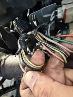
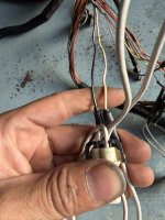
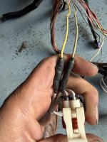
Does anyone have a wiring diagram for a 04 LB7? I've tried Google and searching this forum with no luck. In my truck I have the following wires going to the 7 pin connector on the NSBU.
1. Orange/Black.
2. Pink maybe 16 gauge.
3. Pink maybe 18-20 gauge.
4. Dark Green.
5. Light Green.
6. Black/white.
7. Yellow.
 

dndj

Boost!
Apr 13, 2019
302
33
28
Oregon
This is from my '03, 04 should be same. Sorry, diagram above only had connector C1, I think you're looking for C2. Pinout below. The circuits on C2 appear to be scattered throughout various sections of the manual so let me know if there's a specific circuit you're interested in and I can try and find it.


2.jpg
 
Last edited:

Jsle131

New member
Jan 17, 2022
23
1
3
Thanks for the diagrams. I think 04 is different. Wire colors are all different.
 

Ron Nielson

Active member
Oct 11, 2009
680
113
43
Berryton, KS
Attached is from GMUPFITTER for an LB7 (bottom left corner). It is common for wire colors not to match exactly.
 

Attachments

  • NSBU LB7.pdf
    45 KB · Views: 42

dndj

Boost!
Apr 13, 2019
302
33
28
Oregon
Attached is from GMUPFITTER for an LB7 (bottom left corner). It is common for wire colors not to match exactly.
Yup. Same wiring shown in post #2. C1(J1) is 4 position connector, C2(J2) is 7 position connector, and both carry NSBU circuits (also called Park/Neutral Position Switch in the GM manual).
 

Jsle131

New member
Jan 17, 2022
23
1
3
Using the voltmeter I got the following with the key on.
Orn/blk 10v with truck in P.
2 pink wires 12v all the time.
Yellow wire 12v with truck in N.
Lt grn and drk grn no power.
Blk/wht is ground.

Going off of the functions list, does the following make sense?

A.orn/blk park/neutral signal.
B.lt grn park/neutral position switch signal.
C.pnk ignition voltage.
D.blk/wht ground.
E.pnk starter relay coil
F.drkgrn backup lamp supply voltage? No power to this wire while truck is in R.
G.yel neutral safety switch.
 

03CATEYELB7

New member
Jun 26, 2022
2
0
1
Using the voltmeter I got the following with the key on.
Orn/blk 10v with truck in P.
2 pink wires 12v all the time.
Yellow wire 12v with truck in N.
Lt grn and drk grn no power.
Blk/wht is ground.

Going off of the functions list, does the following make sense?

A.orn/blk park/neutral signal.
B.lt grn park/neutral position switch signal.
C.pnk ignition voltage.
D.blk/wht ground.
E.pnk starter relay coil
F.drkgrn backup lamp supply voltage? No power to this wire while truck is in R.
G.yel neutral safety switch.
Did you ever figure out if this was right?