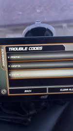
Hey guys, I’m new here and I’m looking for info. I have a 2018 L5P and It has custom tuning and has for the last 2+ years and 25k+ miles, I was driving the other day and it went into limp mode, it’s throwing 3 codes P0046 U18A2 & U0076. I have the can bus dummy plug and nox sensor plugs on the truck. I have replaced all 4 plugs just for safe measure as I live in northern Wisconsin where the salt gets at everything. I called my tuner and they said it’s not a problem with tuning but the truck. I’m thinking maybe it could be a bad turbo actuator? Or could there be just a broken wire somewhere in the harness for the canbus? My fuel gauge does not work, turbo builds no boost and I don’t have enough fuel pressure to get over 2k rpms. Any help and info would be great! Thanks!
You are using an out of date browser. It may not display this or other websites correctly.
You should upgrade or use an alternative browser.
You should upgrade or use an alternative browser.
Do you have the factory modules to plug back in?
You have a wiring problem. Connectors, wiring, or a bad module. Fix the u codes and the p code may go away. The dummy plugs should be easy to check, ask the supplier for the pin outs to see how to test them. Then check for signals on each plug. For the bus trouble shooting it's better to have a scope, but a multi meter with a pulse detector or digital pulse meter will help.
Last edited:
I do not have the factory modules. If I knew where to get some cheap I wouldDo you have the factory modules to plug back in?
It wouldn't do any good to hook up new modules if your ecm has them tuned out. You just need to start tracing wires to see which one is shorted, disconnected, or corroded up.
Or just replace the fuel pump driver control module. Mine had to be replaced earlier this year. Mine was still under warranty so I don't know for sure if it requires programming that module or no. There were others that also had to replace the pigtail to the module as they had arced internally and shorted out module. This one you do still have.
Or just replace the fuel pump driver control module. Mine had to be replaced earlier this year. Mine was still under warranty so I don't know for sure if it requires programming that module or no. There were others that also had to replace the pigtail to the module as they had arced internally and shorted out module. This one you do still have.
2019 Chevy Truck Silverado 3500 4WD V8-6.6L DSL Turbo
Data Communications (L5P)
Vehicle ALL Diagnostic Trouble Codes ( DTC ) Testing and Inspection U Code Charts U18A2 Data Communications (L5P)
DATA COMMUNICATIONS (L5P)
Document ID: 5542132
Diagnostic Instructions
Perform the Diagnostic System Check - Vehicle prior to using this diagnostic procedure.
Review Strategy Based Diagnosis for an overview of the diagnostic approach.
Diagnostic Procedure Instructions provides an overview of each diagnostic category.
DTC Descriptors
DTC U18A2
Lost Communication with Fuel Pump Driver Control Module
For symptom byte information, refer to Symptom Byte List.
Diagnostic Fault Information
Circuit Short to Ground Open/High Resistance Short to Voltage Signal Performance
B+ U18A2 U18A2 — —
Ignition U18A2 U18A2 — —
NOx Sensor 1 Control (circuit 3674) U18A2 U18A2 — —
Fuel Pump Primary Relay Control (circuit 465) U18A2 U18A2 — —
Powertrain High Speed GMLAN Serial Data (+) (circuit 4498)
or High Speed GMLAN Serial Data (+) 7 U0076* U0076* U0076* —
Powertrain High Speed GMLAN Serial Data (-) (circuit 4499)
or High Speed GMLAN Serial Data (-) 7 U0076* U0076* U0076* —
Ground — U18A2 — —
* Other DTCs may set with this fault.
Circuit/System Description
Devices connected to the serial data circuits monitor for serial data communications during normal vehicle operation. Operating information and commands are exchanged among the devices. The devices have prerecorded information about what messages are needed to be exchanged on the serial data circuits, for each virtual network. The messages are supervised and also, some periodic messages are used by the receiver device as an availability indication of the transmitter device. Each message contains the identification number of the transmitter device.
Conditions for Running the DTC
The system voltage is between 9–16 V.
Conditions for Setting the DTC
A supervised periodic message that includes the transmitter device availability has not been received.
Action Taken When the DTC Sets
Specific subsystems will not function.
Conditions for Clearing the DTC
A current DTC clears when the malfunction is no longer present.
A history DTC clears when the device ignition cycle counter reaches the reset threshold of 50, without a repeat of the malfunction.
Reference Information
Schematic Reference
Data Communication Schematics
Control Module References
Connector End View Reference
Master Electrical Component List
Description and Operation
Data Link Communications Description and Operation
Electrical Information Reference
Circuit Testing
Connector Repairs
Testing for Intermittent Conditions and Poor Connections
Wiring Repairs
Scan Tool Reference
Control Module References for scan tool information
Circuit/System Verification
Ignition ON/Vehicle In Service Mode.
Verify DTC U0073, U0074, U0075, U0076, U0077, U0078, U007A, U007B, U007C, U007D, P06E4, P1EB9, U1814, U2099, B1325, B1330, B1370, B1380, B1424, B1428, B1440, B1441, B1517, C0800, C0899, C12E1, P0560, or P0562 is not set.
If any of the DTCs are set
Refer to Diagnostic Trouble Code (DTC) List - Vehicle.
If none of the DTCs are set
Refer to Circuit/System Testing.
Circuit/System Testing
Note: Use the schematics and connector end views to identify the device's ground, B+, ignition, accessory wake up serial data, fuel pump primary relay control, fuel pump controller data out signal, and serial data circuit terminals.
Ignition/Vehicle OFF, all access doors closed, all vehicle systems OFF, and all keys at least 3 m (9.8 ft) away from vehicle. Disconnect the harness connectors at the K111 Fuel Pump Driver Control Module. It may take up to 10 min for all vehicle systems to power down.
Note: If the control module’s chassis ground is shared with any tail lamp assembly, disconnect the harness connector at that tail lamp assembly to remove the alternative path to ground before proceeding with this step.
Test for less than 10 Ω between each ground circuit terminal and ground.
If 10 Ω or greater
Ignition/Vehicle OFF.
Test for less than 2 Ω in the ground circuit end to end.
If 2 Ω or greater, repair the open/high resistance in the circuit.
If less than 2 Ω, repair the open/high resistance in the ground connection.
If less than 10 Ω
Ignition ON/Vehicle In Service Mode.
If equipped, verify a test lamp illuminates between each B+ circuit terminal and ground.
If the test lamp does not illuminate and the circuit fuse is good
Ignition/Vehicle OFF, remove the test lamp.
Test for less than 2 Ω in the B+ circuit end to end.
If 2 Ω or greater, repair the open/high resistance in the circuit.
If less than 2 Ω, verify the fuse is not open and there is voltage at the fuse.
If the test lamp does not illuminate and the circuit fuse is open
Ignition/Vehicle OFF, remove the test lamp.
Test for infinite resistance between the B+ circuit and ground.
If less than infinite resistance, repair the short to ground in the circuit.
If infinite resistance, replace the K111 Fuel Pump Driver Control Module.
If the test lamp illuminates
If equipped, verify a test lamp illuminates between each ignition circuit terminal and ground.
If the test lamp does not illuminate and the circuit fuse is good
Ignition/Vehicle OFF, remove the test lamp.
Test for less than 2 Ω in the ignition circuit end to end.
If 2 Ω or greater, repair the open/high resistance in the circuit.
If less than 2 Ω, verify the fuse is OK and there is voltage at the fuse.
If the test lamp does not illuminate and the circuit fuse is open
Ignition/Vehicle OFF, remove the test lamp.
Test for infinite resistance between the ignition circuit and ground.
If less than infinite resistance, repair the short to ground in the circuit.
If infinite resistance, replace the K111 Fuel Pump Driver Control Module.
If the test lamp illuminates
If equipped, verify a test lamp illuminates between the NOx sensor 1 control circuit terminal (circuit 3674) and ground.
If the test lamp does not illuminate and the circuit fuse is good
Ignition/Vehicle OFF, remove the test lamp.
Test for less than 2 Ω in the ignition circuit end to end.
If 2 Ω or greater, repair the open/high resistance in the circuit.
If less than 2 Ω, verify the fuse is OK and there is voltage at the fuse.
If the test lamp does not illuminate and the circuit fuse is open
Ignition/Vehicle OFF, remove the test lamp, disconnect all devices that share the same NOx sensor 1 control circuit.
Test for infinite resistance between the NOx sensor 1 control circuit terminal and ground.
If less than infinite resistance, repair the short to ground in the circuit.
If infinite resistance
Replace the circuit fuse.
Reconnect the first device that shares the same NOx sensor 1 control circuit.
Ignition ON/Vehicle In Service Mode.
Verify a test lamp illuminates between the NOx sensor 1 control circuit terminal and ground.
If the test lamp does not illuminate and the circuit fuse is open, replace the device that was just connected.
If the test lamp illuminates
Ignition/Vehicle OFF, reconnect another device that shares the same NOx sensor 1 control circuit.
Ignition ON/Vehicle In Service Mode.
Verify a test lamp illuminates between the NOx sensor 1 control circuit terminal and ground.
If the test lamp does not illuminate and the circuit fuse is open, replace the device that was just connected.
If the test lamp illuminates
Repeat steps 6.7-6.9 for the remaining devices until a faulty device is identified. If there is no faulty device, replace the K111 Fuel Pump Driver Control Module.
If the test lamp illuminates
Verify if the K111 Fuel Pump Driver Control Module is equipped with the fuel pump primary relay control circuit (circuit 465).
If equipped
Ignition/Vehicle OFF, remove the test lamp, disconnect the harness connectors at the K20 Engine Control Module.
Ignition ON/Vehicle In Service Mode.
Test for less than 1 V between the fuel pump primary relay control circuit terminal and ground.
If 1 V or greater, repair the short to voltage in the circuit.
If less than 1 V
Ignition/Vehicle OFF.
Test for infinite resistance between the fuel pump primary relay control circuit terminal and ground.
If less than infinite resistance, repair the short to ground in the circuit.
If infinite resistance
Test for less than 2 Ω in the fuel pump primary relay control circuit end to end.
If 2 Ω or greater, repair the open/high resistance in the circuit.
If less than 2 Ω, replace the K20 Engine Control Module.
If NOT equipped
Test for less than 4.5 V between each powertrain high speed GMLAN serial data circuit terminal and ground.
Circuit 4498
Circuit 4499
If 4.5 V or greater
Refer to DTC U0076 to test for a short to voltage.
If less than 4.5 V
Ignition/Vehicle OFF, all access doors closed, all vehicle systems OFF, and all keys at least 3 m (9.8 ft) away from vehicle. It may take up to 10 min for all vehicle systems to power down.
Test for greater than 100 Ω between each powertrain high speed GMLAN serial data circuit terminal and ground.
Circuit 4498
Circuit 4499
If 100 Ω or less
Refer to DTC U0076 to test for a short to ground.
If greater than 100 Ω
Disconnect the harness connectors at the device setting the DTC.
Test for less than 2 Ω in each serial data circuits end to end between the K111 Fuel Pump Driver Control Module and the device setting the DTC.
Circuit 4498
Circuit 4499
If 2 Ω or greater
Repair the open/high resistance in the serial data circuit.
If less than 2 Ω
Replace the K111 Fuel Pump Driver Control Module.
Ignition/Vehicle OFF, all access doors closed, all vehicle systems OFF, and all keys at least 3 m (9.8 ft) away from vehicle. It may take up to 10 min for all vehicle systems to power down.
Ignition ON/Vehicle In Service Mode.
Verify DTC U18A2 does not set again.
If DTC U18A2 sets
Replace the K20 Engine Control Module.
If DTC U18A2 does not set
All OK.
Repair Instructions
Perform the Diagnostic Repair Verification after completing the repair.
Control Module References for device replacement, programming and setup

Question
Yesterday morning, got a call from my dad that his truck wouldn't start (2018 L5P) when he got off work. He told me over the phone that it was turning over but that it didn't seem like it was getting any Fuel. No big deal as I'm on the other side of the plant working nights with him. I pull up...
 www.duramaxdiesels.com
Might help....