Another PSC install along with 2011 hydroboost and all new PS lines.

firestopper

New member
Nov 27, 2020
16
8
3
Backround:
Ive own my 05 Sierra 2500HD since new and have done many modifications over the years. Non of which have negatively impacted the drivability or reliability of the rig. I only use it for hauling steel and occasionally for travel. The rig currently has 95K on the clock.

The power steering hoses have been "wheeping" for some time and the Hydroboost developed a drip between the brake master and said booster. I live in SW Arizona so triple digit temps are a regular theme. I was beside myself to discover the absence of a PSC on a rig designed to tow. My wife's 1/2 ton Z-71has a tranny and PSC from birth.....Go figure.

First order of business was to flush out the old fluid and any potential contaminates.


I used some inexpensive PS fluid for the flush and will use the Valvoline after the components are replaced. The only component in the system that will remain is the pump, that being said I wanted to ensure it was cleaned out and free of older burnt fluid.
IMG_0898.jpeg
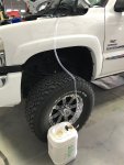
The set up was simple, I had the rigs front tires just off the ground, a line coming from the hydroboost return to a container. With the rig running, I turned the wheels right to left while pumping the brakes making sure to continually keep the reservoir full. The fluid coming out was nasty and dark. I have flushed this system out twice in the past so I was a bit surprised in the condition of the fluid.
IMG_0899.jpeg
After the entire gallon of the inexpensive PS fluid I had good clean fluid.
IMG_0900.jpeg
Next up, removing the front grill to clean out the cooling stacks.
 

Attachments

  • IMG_0896.jpeg
    IMG_0896.jpeg
    1.7 MB · Views: 22
  • Like
Reactions: 1TRIKHD

firestopper

New member
Nov 27, 2020
16
8
3
The cooling stack was degreased and all debris was flushed out. The rigs drivers side inner fender was removed as was the intercooler pipe allowing access to the top of the steering box. The new cooler (Dorman $60 Amazon ) was mocked up but I didn't like how close the coolers tubes/hoses came to the lower side of the intercooler. I once worked on fighter aircraft so Im very familiar with chaffing issues from lack of proper routing , clamping or adding a buffer where contact can't be avoided. I decided to mount the vertical cooler to the right of the intended mounting location. A lower bracket was required to support the bottom. The top of the cooler mounting tab was trimmed slightly allowing it to fit in-between the original mounting location and the headlight assembly support bracket.

IMG_3457.JPG
Hear, you can see the clearance on the coolers lines entering the engine compartment.
IMG_3458.JPG
The return line (outboard) on the steering box was pulled and the crimped fitting was split allowing the hard line and the hose to be separated. I also opted to cut down the hard line allowing the cooler hose more of a direct access point. I used a flaring tool to create a slight double flare for the new hose to be held securely with SS clamp. While this was removed the inboard high pressure line was also replaced and routed to the hydro-booster. The second new line from the HB to the rear of the pump was also replaced. This was a slight PITA as its congested. The small clamp (13mm bolt) was transferred overt the new clamp and secured to the frame rail.

The lines going into the steering pump. Notice the clearance around the intercooler tube. The cut down line (out board return) also allows the tube to be rotated to ensure clearance.
IMG_3466.JPG
The back of the pump shows the new line routed around a loomed section as well as the second return hose from the new cooler.
IMG_3460.JPG
Lastly a couple of shots of the hydroboost end with the new lines installed.
IMG_3462.JPGIMG_3463.JPG
I'm hoping the addition of the PSC the lines will last longer without seeping etc and the new fluid will also last as well as the new hydrobooster.
The rigs front tires again were off the ground and new fluid (Valvoline) was added while purging the system of air and conducting a leak check.
One thing I noticed was the larger loom protecting the main harness has become extremely brittle. I plan on replacing all the brittle loom and de-greasing the entire area prior to reassembling the inner fender.
The Hydroboost install was not documented as I was "in the moment" and contorted under the dash. I will also add the brake pedal rod was enlarged slightly allowing the brake switch to function as intended.

Tip, when removing old lines, ensure the O-rings are accounted for and NOT left inside the ports. Ensure the NEW O-rings are lubed and DO NOT OVER TORQUE the new lines. Second tip, use something to cap off the new lines when routing them in place. This process requires rotation and snaking the lines into location. This can easily result in unwanted debris from contaminating the ends of the lines. I have an assortment of hydraulic fitting (caps) and capped the ends avoiding contamination. Never replace components without first flushing. This includes cooling, brake, PS systems. Too many times have water pumps been replaced due to weeping seal only for the new pump fail within months because the coolant wasn't flushed.
Going forward, I look forward to sharing more modifications from the past.
Turn and Burn!
 

firestopper

New member
Nov 27, 2020
16
8
3
Thanks rcr1978, thanks Ron, the rig lived outside for the first seven years of her life so wax on wax off twice a year.
Heres a few shots from earlier today after I replaced the rotted loom behind the drivers side inner fender well.

The larger diameter loom for the main harness has an O.D. of 1.250". No local automotive parts house would sell by the foot and I certainly didn't need 100'.
I was able to source it at a electrons warehouse along with the correct tape.
IMG_3467.JPG
The tape is extremely sticky and has fiber impregnated material for durability.
IMG_3471.JPG
The old brittle 1-1/4" loom removed and the new loon taped in with the correct plastic anchors to be attached to the inner fender well.
IMG_3469.JPGIMG_3470.JPG
A few shots of the rig. She has been lifted (6" FabTech) since she was a couple of months old.


IMG_3472.JPG
Tucked under the rockers are Amp Research power boards. The rig also has a MSD super chip, MSD propane injection (with computer), aFe cold air intake, aFe 4" turbo back exhaust, EGR blocking plate, finger stick to name a few performance upgrades. The rig has passed emissions every year without fail and runs well.
IMG_3474.JPG
I built the rear bumper and tire carrier back in 06. The tire carrier swings out like most but it also kneels to the ground eliminating the need to hold up the heavy tire when indexing the lugs. I'm too old to wrestle large awkward items. :) The backup camera works with a Denali entertainment system taken from a 2006.
This required running 13 new circuits, GPS antenna, speed sensor (in dash), replacing the Bose Amp and head unit. I also added a six CD changer (same diner Denali). 23 wires required repining (reconfiguring) and lastly the dealer to program the VIN. BTY, these rigs that came stock with the Bose Premium sound system also came with a sub woofer that was not tied into the sound system circuit. When I swapped everything out to the Bose Luxury sound system found in Denali's and Escallades the woofer came to life. The dealer service rep had doubts but when I handed him detailed instructions for the tech II programming he took my $98 and five minutes later it all worked as planned. Still running XM (under dash factory module) for those remote areas when traveling. The A-pillar cluster monitors EGT, Propane level and Air pressure for the air system inside the front bumper. It supplies the airbags (rear) and the 153 decibel locomotive triple horn stashed under the bed facing backwards.
Thanks for looking!
IMG_3475.JPG
 
  • Like
Reactions: CarolinaHD