My glow plugs aren't working, I just installed new GM glow plugs and it still doesn't start worth a Cr@p when it gets below 30 degrees. I clamp metered my power wire to the glow plugs and its not pulling any amps. Does anyone have the proper way to test the factory controller and wiring diagram or should I just throw it away and put a solid state relay on since I don't have a intake heater. I put a brand new GM controller 40K miles ago, hopefully its just wired wrong.
LB7: Glow plug Controller???
- Thread starter MAXX IT OUT
- Start date
You are using an out of date browser. It may not display this or other websites correctly.
You should upgrade or use an alternative browser.
You should upgrade or use an alternative browser.
Sub'd, I think I'm having GP wiring issues as well. Mine does the same thing but seems like only one bank is working.
My intake heater works fine.
My intake heater works fine.
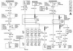
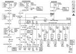
I'm guessing you have a Federal truck, not CA? I attached the CA schematic just in case.
The Federal system is really easy to diagnose. It is just a large, custom, unreliable relay, but relays are simple. The CA system is harder to diagnose (in some ways), but far more reliable since it is all solid state. Anyway, what you want to do, in vaguely this order, is:
For Bdsankey, if you feel only one bank is working, trace the wiring between all the glow plugs. They run a bus bar on each bank with a link between the two banks. The bus bars love to corrode off, which disables any glow plugs downstream of the break.
The Federal system is really easy to diagnose. It is just a large, custom, unreliable relay, but relays are simple. The CA system is harder to diagnose (in some ways), but far more reliable since it is all solid state. Anyway, what you want to do, in vaguely this order, is:
- Check for +12V on the output of the 175 amp glow plug fuse in the fuse block. I believe this is on the side of it nearest the front of the truck. If you don't have power here at all times, replace the fuse.
- Check for +12V on the input terminal of the glow plug controller. If you don't have power here, replace the wire connecting the fuse to the glow plug controller. I can't find a part number for this, but you could easily make a custom one the right size.
- Have a friend key-on the truck while you measure the glow plug output terminal. If it goes to +12V, your problem is downstream. If it stays at 0V, the controller or wiring is bad. If you want to just replace the controller, Federal part #97371491 is $133 for OE and $94 for a Doorman.
- If the controller is fine, just start tracing the glow plug wires/bus bars to find where it stops getting power. Replace as needed.
- If the controller is NOT working:
- Take the controller apart. There are 2 relays inside. Find the one connected to the glow plug output post, and disconnect it.
- Measure the 4 pins to diagnose if the relay or wiring is bad.
- First big pin should be +12V from the battery. If not, the internal harness of the glow plug controller is bad, replace the controller.
- Second big pin should show continuity to the glow plug output post. If not, the internal harness of the glow plug controller is bad, replace the controller.
- One small pin should be a good ground. If not, start tracing back and repair the ground.
- The other is the enable from the ECU. Have a friend key-on the truck and make sure this pin goes to +12V while the glow plug light is on (it may stay at +12V longer than the glow plug light, this is fine). If not, unplug the controller from the truck and check the pin on the plug where it connects to the engine harness.
- If the engine harness has the enable signal, the internal harness of the glow plug controller is bad, replace the controller.
- If the engine harness doesn't have the enable signal, start tracing it back to the Bale connectors (C107 pin A2) and ECU (C2 pin 6). Repair as necessary.
- If the signals are all present, the relay is bad. Replace the relay.
For Bdsankey, if you feel only one bank is working, trace the wiring between all the glow plugs. They run a bus bar on each bank with a link between the two banks. The bus bars love to corrode off, which disables any glow plugs downstream of the break.
Attachments
I'm guessing you have a Federal truck, not CA? I attached the CA schematic just in case.
The Federal system is really easy to diagnose. It is just a large, custom, unreliable relay, but relays are simple. The CA system is harder to diagnose (in some ways), but far more reliable since it is all solid state. Anyway, what you want to do, in vaguely this order, is:
Odds are the relay inside the controller is shot. You can buy a new relay for cheap (DORMAN 904100 is $28), or, since it sounds like you don't use the intake air heater, swap the 2 relays inside the controller to get a bit more life out of it.
- Check for +12V on the output of the 175 amp glow plug fuse in the fuse block. I believe this is on the side of it nearest the front of the truck. If you don't have power here at all times, replace the fuse.
- Check for +12V on the input terminal of the glow plug controller. If you don't have power here, replace the wire connecting the fuse to the glow plug controller. I can't find a part number for this, but you could easily make a custom one the right size.
- Have a friend key-on the truck while you measure the glow plug output terminal. If it goes to +12V, your problem is downstream. If it stays at 0V, the controller or wiring is bad. If you want to just replace the controller, Federal part #97371491 is $133 for OE and $94 for a Doorman.
- If the controller is fine, just start tracing the glow plug wires/bus bars to find where it stops getting power. Replace as needed.
- If the controller is NOT working:
- Take the controller apart. There are 2 relays inside. Find the one connected to the glow plug output post, and disconnect it.
- Measure the 4 pins to diagnose if the relay or wiring is bad.
- First big pin should be +12V from the battery. If not, the internal harness of the glow plug controller is bad, replace the controller.
- Second big pin should show continuity to the glow plug output post. If not, the internal harness of the glow plug controller is bad, replace the controller.
- One small pin should be a good ground. If not, start tracing back and repair the ground.
- The other is the enable from the ECU. Have a friend key-on the truck and make sure this pin goes to +12V while the glow plug light is on (it may stay at +12V longer than the glow plug light, this is fine). If not, unplug the controller from the truck and check the pin on the plug where it connects to the engine harness.
- If the engine harness has the enable signal, the internal harness of the glow plug controller is bad, replace the controller.
- If the engine harness doesn't have the enable signal, start tracing it back to the Bale connectors (C107 pin A2) and ECU (C2 pin 6). Repair as necessary.
- If the signals are all present, the relay is bad. Replace the relay.
For Bdsankey, if you feel only one bank is working, trace the wiring between all the glow plugs. They run a bus bar on each bank with a link between the two banks. The bus bars love to corrode off, which disables any glow plugs downstream of the break.
I just put in all new ACDelco glow plugs and buss bars. I think I may have it wired incorrectly. My truck has 4 total wires at the glow plug module for its two terminals (excluding the hot input). I think I have it messed up there after I did injectors and had that all apart.
My drivers side bank has 2 wires, on on cyl 8 and one on cyl 2. The passenger side bank has 1 wire on it at cyl 1 feeding the bank.
That sounds right, but I rarely mess with federal trucks. I will have to look at my brother's truck when I get some free time. You can just grab a multimeter and start probing continuity to make sure they are all actually connected together correctly. I think the wire on #2 should feed across to #1, so make sure that has continuity and isn't broken internally.I just put in all new ACDelco glow plugs and buss bars. I think I may have it wired incorrectly. My truck has 4 total wires at the glow plug module for its two terminals (excluding the hot input). I think I have it messed up there after I did injectors and had that all apart.
My drivers side bank has 2 wires, on on cyl 8 and one on cyl 2. The passenger side bank has 1 wire on it at cyl 1 feeding the bank.
That sounds right, but I rarely mess with federal trucks. I will have to look at my brother's truck when I get some free time. You can just grab a multimeter and start probing continuity to make sure they are all actually connected together correctly. I think the wire on #2 should feed across to #1, so make sure that has continuity and isn't broken internally.
Sounds good. I was more so trying to figure out where the 4 wires went across the 2 terminals that are there. I know one is for the intake heater (which I still have and plan on leaving, not looking to make any big power) but I don't know where everything else goes.
You should have the following:Sounds good. I was more so trying to figure out where the 4 wires went across the 2 terminals that are there. I know one is for the intake heater (which I still have and plan on leaving, not looking to make any big power) but I don't know where everything else goes.
- B+ input post: 1 large wire coming from 175 amp fuse
- Glow plug output post: 1 large wire to the glow plug bus bar & 1 small wire for feedback to the ECU. The small wire goes to a strange round plug right near the controller.
- Intake air heater out post: 1 large wire to the intake air heater & 1 small wire for feedback (same as glow plugs).
You should have the following:
So if you have ! large & 1 small wire on each output, that is correct.
- B+ input post: 1 large wire coming from 175 amp fuse
- Glow plug output post: 1 large wire to the glow plug bus bar & 1 small wire for feedback to the ECU. The small wire goes to a strange round plug right near the controller.
- Intake air heater out post: 1 large wire to the intake air heater & 1 small wire for feedback (same as glow plugs).
I am about 100% confident I have it wired wrong then. I think I have both feedback wires on one terminal (glow plug terminal) but it doesn't throw codes.
The LB7 federal tune basically won't throw codes for the glow plug or intake heater at all. I honestly don't know why they even added those feedback wires.I am about 100% confident I have it wired wrong then. I think I have both feedback wires on one terminal (glow plug terminal) but it doesn't throw codes.
The LB7 federal tune basically won't throw codes for the glow plug or intake heater at all. I honestly don't know why they even added those feedback wires.
I'll have to look and check things out. I appreciate the help. Its got 257k miles on it and it doesn't appreciate starting in the cold much but once its running it doesn't have excessive blow by and runs smooth/gets good economy. I ran the valves when I did injectors and everything is good to go there.
The LB7 federal tune basically won't throw codes for the glow plug or intake heater at all. I honestly don't know why they even added those feedback wires.
I know the federal lb7’s throw a code if the AIH is unbolted. Don’t know about if it does when it doesn’t work though.
The LB7 federal tune basically won't throw codes for the glow plug or intake heater at all. I honestly don't know why they even added those feedback wires.
Not 100% true. My fuse was blown and my engine light was in till I figured it out.