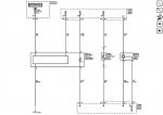
Here is the layout for the p0128 code just incase, alot with the pinout for the sensor, and the wiring for the sensor as well. Hope it helps. (the image attached is the wiring diagram)
Engine Coolant Temperature (ECT) Sensor
Pin
Wire
Circuit
Function
Pin A
0.35 BLACK
2761
Low Reference
Pin B
0.35 YELLOW
410
ECT Sensor Signal
Service Information Home Publications Number Search New Bulletins Bulletin Search Feedback Help
2008 GMC Truck Canyon Pickup - 2WD | Canyon, Colorado, I-290, I-370 VIN S/T Service Manual | Document ID: 1972216
DTC P0128
Diagnostic Instructions
Perform the Diagnostic System Check - Vehicle prior to using this diagnostic procedure.
Review Strategy Based Diagnosis for an overview of the diagnostic approach.
Diagnostic Procedure Instructions provides an overview of each diagnostic category.
DTC Descriptor
DTC P0128
Engine Coolant Temperature (ECT) Below Thermostat Regulating Temperature
Diagnostic Fault Information
Circuit
Short to Ground
High Resistance
Open
Short to Voltage
Signal Performance
ECT Sensor Signal
P0117
P0118
P0118
P0118
P0116, P0128
Low Reference
—
P0118
P0118
P0118
P0128
Typical Scan Tool Data
ECT Sensor
Circuit
Short to Ground
Open
Short to Voltage
Operating Conditions: Engine running at various operating conditions
Parameter Normal Range: Varies with coolant temperature
ECT Sensor Signal
150°C (302°F)
−40°C (−40°F)
−40°C (−40°F)
Low Reference
—
−40°C (−40°F)
−40°C (−40°F)
Circuit/System Description
The engine coolant temperature (ECT) sensor is a variable resistor that measures the temperature of the engine coolant. The engine control module (ECM) supplies 5 volts to the ECT sensor signal circuit and a ground for the low reference circuit.
The purpose of this diagnostic is to analyze the performance of the thermostat, by using the ECT sensor to determine if the engine coolant will increase at the correct rate, and also meet the calibrated target temperatures under various operating conditions. The ECM uses the start-up ECT and the start-up intake air temperature (IAT) to begin the diagnostic calculation. The air flow into the engine is accumulated , and vehicle speed, distance, and engine run time are also factored in to determine if the ECT does increase normally and reach the calibrated target temperatures.
Conditions for Running the DTC
DTC P0101, P0102, P0103, P0106, P0107, P0108, P0112, P0113, P0116, P0117, P0118, P0121, P0122, P0123, P0502, or P0503 is not set.
The start-up ECT is colder than 65°C (122°F) when the start-up IAT is colder than 10°C (50°F).
OR
The start-up ECT is colder than 75°C (167°F) when the start-up IAT is warmer than 10°C (50°F).
The start-up IAT is between −7 to +55°C (+19 to +131°F).
The engine run time is between 30 seconds and 30 minutes.
The vehicle has traveled greater than 0.8 kilometers (0.5 miles) at greater than 8 km/h (5 mph).
The mass air flow (MAF) average is greater than 1 g/s.
This DTC runs once per ignition cycle within the enabling conditions.
Conditions for Setting the DTC
The ECM detects that the maximum amount of cumulative airflow has been attained, and the minimum ECT of 70°C (158°F) has not been reached with a start-up IAT colder than 10°C (50°F).
OR
The ECM detects that the maximum amount of cumulative airflow has been attained, and the minimum ECT of 80°C (176°F) has not been reached with a start-up IAT warmer than 10°C (50°F).
Action Taken When the DTC Sets
DTC P0128 is a Type B DTC.
Conditions for Clearing the MIL/DTC
DTC P0128 is a Type B DTC.
Diagnostic Aids
DTC P0128 occurring with insufficient vehicle interior heating is an indication of improper thermostat operation.
Corrosion in the ECT sensor terminals or the ECT harness connector results in a greater voltage on the ECT sensor signal circuit, which is interpreted by the ECM as a colder ECT.
A slight to moderate resistance in the ECT sensor signal circuit or low reference circuit will affect this diagnostic. This condition results in a greater voltage on the ECT sensor signal circuit, which is interpreted by the ECM as a colder ECT.
Reference Information
Schematic Reference
Engine Controls Schematics
Connector End View Reference
Component Connector End Views
Electrical Information Reference
Circuit Testing
Connector Repairs
Testing for Intermittent Conditions and Poor Connections
Wiring Repairs
DTC Type Reference
Powertrain Diagnostic Trouble Code (DTC) Type Definitions
Scan Tool Reference
Control Module References for scan tool information
Circuit/System Verification
Ignition OFF, inspect the cooling system surge tank for the proper coolant level. Refer to Cooling System Leak Testing and Cooling System Draining and Filling.
Ignition OFF for 8 hours or greater.
Ignition ON, observe the scan tool ECT Sensor and IAT Sensor parameters. The ECT, IAT and ambient temperatures should be within 15°C (27°F) of each other.
Important: A critical analysis of the operation of the thermostat is necessary to properly diagnose this DTC.
Verify the proper heat range, and the operation of the thermostat. Refer to Thermostat Diagnosis.
Operate the vehicle within the Conditions for Running the DTC to verify the DTC does not reset. You may also operate the vehicle within the conditions that you observed from the Freeze Frame/Failure Records data.
Circuit/System Testing
Ignition OFF, disconnect the harness connector at the ECT sensor.
Ignition OFF for 90 seconds, test for less than 5 ohms between the low reference circuit terminal A and ground.
If greater than the specified range, test the low reference circuit for an open/high resistance. If the circuit tests normal, replace the ECM.
Ignition ON, verify the scan tool ECT Sensor parameter is colder than −39°C (−38°F).
If warmer than the specified range, test the signal circuit terminal B for a short to ground. If the circuit tests normal, replace the ECM.
Install a 3A fused jumper wire between the signal circuit terminal B and the low reference circuit terminal A. Verify the scan tool ECT Sensor parameter is warmer than 149°C (300°F).
If colder than the specified range, test the signal circuit for a short to voltage or an open/high resistance. If the circuit tests normal, replace the ECM.
If the circuits test normal, test or replace the ECT sensor.
Component Testing
Measure and record the resistance of the ECT sensor at various ambient temperatures, then compare those measurements to the Temperature Versus Resistance table .
Repair Instructions
Perform the Diagnostic Repair Verification after completing the diagnostic procedure.
Engine Coolant Temperature Sensor Replacement
Engine Coolant Thermostat Replacement
Control Module References for ECM replacement, setup, and programming
© 2015 General Motors. All rights reserved.