Swapping Passenger Manual Seat for Full Power/Heated/Lumbar

fl0w3n

Active member
Jan 8, 2015
508
25
28
I was muddying up my own thread so I wanted to start a dedicated one, hopefully I can sort the answer out here and people looking to do the same swap in the future can search and find this instead. Basically it's just capturing my thinking out loud, hoping for input from the wizards here, and trying to sort it all out.

Like the title says, I want to swap my current 4 way power driver & manual passenger for 8 way power with heated function for both driver and passenger. I don't care whether the memory function works or not.

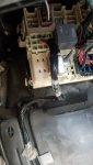
Okay I got kinda lucky and the guy who was selling the seats cut them out on the body side of the harness, so I at least have the connector to go into the passenger seat. I wish I could have taken the whole harness but oh well.

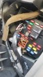
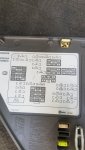
I am looking at C399 for passenger seat, but what's weird to me is it doesn't fully match what All Data is telling me. Is this common because of variance in options or am I just looking at the wrong thing?

From the perspective of my connector (I know it's reversed in my picture, but you can't tell wire color from head on)
A-D matches
E-F doesn't match
G-H matches, but why is there two H's?
J-L doesn't match and doesn't make sense

When looking at the connector call out, going from J-S doesn't even make sense, why skip N and O on the connector lettering?

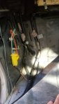
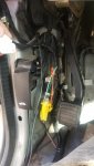
I see Ground #304 under the seat, but I don't see a ground pin in C399, so how is the seat grounded?C399 Connector.jpg1607471198243.png

Green check means matches what I have
Red X means doesn't match what I have
Pin J doesn't make sense, color doesn't match and judging by gauge I assume its another power/ground
1607550439332.png
1607550466571.png
 
Last edited:

fl0w3n

Active member
Jan 8, 2015
508
25
28
I'm unsure of where C399 goes to after, but I think it ties into C305 for the passenger side. Am I correct to assume I would be tie'ing these wires into C305 since they show they are the same circuit? If so, I don't know where the other remaining wires go.

C305 driver on the left, C399 passenger on the right. Color coded to wire color and matching circuit # between both connectors.

1607549823973.png
 

fl0w3n

Active member
Jan 8, 2015
508
25
28
Again, from driver seat... not sure where it goes from here. But, if all I'm doing is tieing passenger to driver like I said above, I guess I don't care where it goes from here.
1607472810046.png1607472919395.png
 

fl0w3n

Active member
Jan 8, 2015
508
25
28
Apparently they came out of an 07 classic Silverado Duramax, and I'm adding them to an 04 Sierra

I started poking around inside my truck yesterday and this is going to be more work than I thought. I was anticipating the driver seat body harness would at least have all the correct wires, but I only found power/ground/seat belt and I think one other.

I was originally hoping driver side would be plug and play and then to just add to the wiring harness by tieing passenger side to driver side and then bringing the appropriate power/class 2 up to the dash, but now it seems like I'd be doing much more wiring than that.

I'm currently looking for a full harness that had the power/heated/memory seats and found a few potentials a couple hours away from a Suburban and a Tahoe and I think one truck. I'll have the truck inside apart anyways, so replacing the harness hopefully isn't that cumbersome and then it should just become plug and play, and from my research I potentially would just need a BCM flash for memory seats (which I don't really care about anyways) and there is a slim chance I need a BCM flash for just heated seats too.
 

1FastBrick

Well-known member
Dec 1, 2016
2,184
805
113
Junkyard
Apparently they came out of an 07 classic Silverado Duramax, and I'm adding them to an 04 Sierra

I started poking around inside my truck yesterday and this is going to be more work than I thought. I was anticipating the driver seat body harness would at least have all the correct wires, but I only found power/ground/seat belt and I think one other.

I was originally hoping driver side would be plug and play and then to just add to the wiring harness by tieing passenger side to driver side and then bringing the appropriate power/class 2 up to the dash, but now it seems like I'd be doing much more wiring than that.

I'm currently looking for a full harness that had the power/heated/memory seats and found a few potentials a couple hours away from a Suburban and a Tahoe and I think one truck. I'll have the truck inside apart anyways, so replacing the harness hopefully isn't that cumbersome and then it should just become plug and play, and from my research I potentially would just need a BCM flash for memory seats (which I don't really care about anyways) and there is a slim chance I need a BCM flash for just heated seats too.
It is easiest, Obviously, if you get the Seat harness. The seat plug changed from the 2003-05 to the 06-07 classic Just so you are aware. Keep those pigtails from the 07 and you can swap the ends. Its a minor change but a pain nonetheless....

From what I remember, the seat harness plugs in around the lower left footwell/ A-Pillar area. it ran down the rocker pinch weld and then across under the seat. from there it went over the center transmission tunnel and to the passenger seat. If I recall there was a Stud ground on the floor. There is also an Air bag module mounted to the floor under the carpet on the drive seat I believe.

I know there is some minor differences in the SUV harness. I am not sure if that is because of the side airbags in the seats or what.

I have been told with the harness the heated seat is plug and play, no need to reprogram. The heat switch on the door panel just plugs into the window switch.
 

fl0w3n

Active member
Jan 8, 2015
508
25
28
Great to know on the switchover, thanks for that.

I found a photo of the right harness from another guy who did the swap, but this photo (red markups are mine) is about the most useful thing I got from his thread unfortunately. This seems to correlate with what you're saying, but...
  • Is the seat circuit only from seat harness to seat harness to the connector I'm pointing at (traced in red)? Or does it tie in with other connectors shown in this harness. If this is all, then that's not that bad to custom make since I have both connectors and I'm sure I can find the crimp ends to just add the wires in the harness
  • If I didn't have the right wires even in the driver side harness, I probably don't have the right wires to go from door panel window junction to IP junction. So even if I do run the above wiring myself, I won't be able to control it without running wire from door window junction at both passenger and driver back to what I'm assuming would be the IP Junction

Here is a photo of the harness, and I identified what I think are the connectors and ground. I'm assuming it ties into the IP junction box where I'm pointing.
1607626000364.png


But... I can't find any more info on the junction block in Alldata yet other than this
1607626048088.png
And of course the diagram from the panel on my truck -
1607626076844.png
 

1FastBrick

Well-known member
Dec 1, 2016
2,184
805
113
Junkyard
I have never Physically taken that harness apart. As you can see it has the Airbag Module and a few airbag Connections tied in. Anything Yellow Is Airbag related.

Yes that Junction box is the tie in point. I would have to look at my truck as I believe its not showing a connection point.
 

1FastBrick

Well-known member
Dec 1, 2016
2,184
805
113
Junkyard
Found the discrepancy. The brown plug does not go to that connection point. It plugs into the left dash fuse block. I think the blue conector goes to the BCM.

Seat harnnes correction.png
 

1FastBrick

Well-known member
Dec 1, 2016
2,184
805
113
Junkyard
See if this helps. I don't know what each connection point's actually does.
 

Attachments

  • 20201210_132340.jpg
    20201210_132340.jpg
    395.5 KB · Views: 10
  • 20201210_132329.jpg
    20201210_132329.jpg
    509.9 KB · Views: 9
  • 20201210_132427.jpg
    20201210_132427.jpg
    486.6 KB · Views: 9
  • 20201210_132407.jpg
    20201210_132407.jpg
    623.7 KB · Views: 9
  • 20201210_132523.jpg
    20201210_132523.jpg
    548.4 KB · Views: 9

fl0w3n

Active member
Jan 8, 2015
508
25
28
Okay that does actually help. I think you're on the right track, left dash fuse block 12 pin connector seems to be one of them, but according to what I'm now seeing there should be more connections.

If that's the case, then this is the routing.
I think #4 is mislabeled as G399 when it's C399, connector for passenger seat.
Then it goes over to #12, C305 which is drivers seat.
Then I believe what you're showing in the left dash fuse block is Relay Block - I/P C10. IP C10 shows passenger seat airbag so clearly that's the right track, but nothing about signal for seat heat.
1607642924177.png


1607643199257.png
 

1FastBrick

Well-known member
Dec 1, 2016
2,184
805
113
Junkyard
I think the #16 IP C10 is the footwell Plug with the White connector.
I think #1 IP Fuse Block I/P C4 is the left dash Plug Brown Connector.

Look in to #18 Which I believe is the Blue plug on the harness In the picture you first brought in.
 

fl0w3n

Active member
Jan 8, 2015
508
25
28
This is as far as I can get tonight, my eyes are starting to water from staring at so many circuit numbers trying to trace everything.

The circuit from passenger to driver connector is easy, but I can only find 4 connections from driver to the rest of the body - power, Class 2 Serial Data, Seat Position Switch, and Seat Belt Indicator.
 

Attachments

  • Circuit Trace Diagram.pdf
    1.1 MB · Views: 6

fl0w3n

Active member
Jan 8, 2015
508
25
28
I think the #16 IP C10 is the footwell Plug with the White connector.
I think #1 IP Fuse Block I/P C4 is the left dash Plug Brown Connector.

Look in to #18 Which I believe is the Blue plug on the harness In the picture you first brought in.
I'll look again in a bit, but I'm not seeing anything on #18 that shares a circuit with the seats. Totally possible I'm glazing over it right now because I've been staring too long haha.
 

1FastBrick

Well-known member
Dec 1, 2016
2,184
805
113
Junkyard
I'll look again in a bit, but I'm not seeing anything on #18 that shares a circuit with the seats. Totally possible I'm glazing over it right now because I've been staring too long haha.
Haha, Looks like you are getting somewhere now!
 

fl0w3n

Active member
Jan 8, 2015
508
25
28
Haha, Looks like you are getting somewhere now!
I feel like one of those crazy detectives with the pictures up on the board trying to crack a case.

So I think I've made some progress on my understanding at least of what's going on. A lot of help in understanding of function from this thread (sorry if cross posting forums is not allowed here) - GM Truck Forum

Trying to write this out is hard but here it goes, flow from passenger switch to passenger butt actually getting warm
- Passenger hits switch on door panel, there's 8 wires from switch to PDM, but PDM converts the signal and the signal is carried on one wire - Circuit 1047 "PDM Class 2 Serial Data"
-Circuit 1047 leaves FPDM Connector 2 @ Pin 22 and travels to Junction Block I/P @ Pin 7B
-Circuit 1047 leaves Jucntion Block I/P @ Pin 7B and while traveling through dash, gets picked up by Splice Pack SP205 (Note: Circuit 1048 is NOT one that is picked up here)
- From this splice point, I have yet to find out it gets to C223
- From C223 - I/P Harness to Body Harness @ Pin A (at driver kick panel) we pickup circuit 1048 "SCM (Seat) Class 2 Serial Data (AG2)" and I assume this carries the signal to C305 Body Harness to Drivers Seat Harness @ Pin D
- C305 Body Harness to Driver Seat Harness @ Pin D circuit 1048 carries the signal to Memory Seat Module Connector #4 Pin 9 Circuit 1048.
- Memory Seat Module then triggers supply voltage over one of the circuits, i.e. Connector #4 Pin 11 Circuit 2479 "Passenger Heated Seat Element Supply Voltage"
-Toasty buns


So, it looks like I need to-
-Run one wire from passenger door to passenger kick panel I/P (Circuit 1047)
-Figure out how signal gets from circuit 1047 to 1048 and confirm that infrastructure already exists (i.e. no wire needed from me)
-Run one wire from driver kick panel I/P to Memory Seat Module (Circuit 1047)
-Figure out/presumably run one wire from driver door to driver kick panel, and possibly from kick panel to Memory Seat Module

Then there's the power and grounds, which should be fairly straight forward.

So best case hopefully I'm only looking at running 3 comm wires and a couple power/ground wires.